Fighter VTOL 4+1 fixed wing

You can also take a video, I will see the specific flight situation

Hi @Jed_Freeman , @makeflyeasy
Can you share PID setting (or parameter file) based on the latest Arduplane FW (4.1.7)? I am worried that the old default PID (as shared by @GregCovey and MFE) needs to be changed (or modified or recalculated) if we use 4.1.7 FW…

@GregCovey , did you change PID setting when you updated to the latest 4 1.7 FW ?
Thank you…

1 Like

Hello,

You can refer to the official 4.0X to 4.1X parameter conversion software
https://uav.tridgell.net/convert_pid.html

2 Likes

Hi, I have to buy this kit (Pixsurvey Cube V3 Aerial Survey Autopilot Kit VTOL Autopilot Kit|Toy Sports| - AliExpress) but I don’t find anything on web without Ali express that ship from China, anyone know if there is some shop in Europe for this things? Thanks to everyone

@makeflyeasy , Chang,
Thank very much… Based on your Default parameter for Vtol Fighter, I have recalculated using @tridge calculator or conversion… After that I did Autotune for Plane , and finally I got very good tuning result… I use 6S configuration and your Fighter performs excellent and efficient…

2 Likes

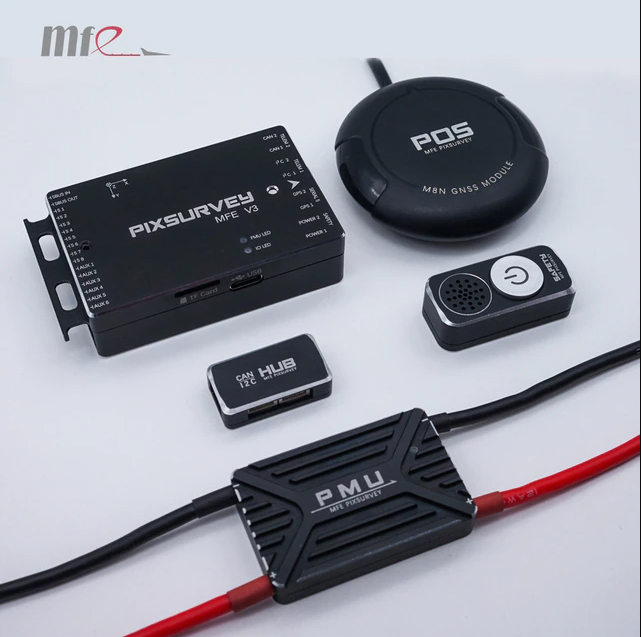
The MFE team released a FMU v3 flight controller, you can learn more through the link below.
https://discuss.ardupilot.org/t/a-pixsurvey-v3-flight-controller-is-recommended-developed-based-on-fmu-v3-which-is-more-suitable-for-vtol-aerial-survey/83700

1 Like

Hi Tim,

Did you ever find out / measure any glide ratio info?
I’m just completing a safety case in the UK and would like to include some glide performance information for the Fighter VTOL. I’m not going to be able to experiment with ours for weeks, which I ultimately will do.
Thanks,
Alex.

After a delay of nine months I could finally start building the MFE Fighter. For more than half a year I had no real workshop, because my basement was flooded last year by the flood in Central Europe. I was lucky that it only hit the basement. At the turn of the year the basement was renovated and in February I could start to rebuild the small workshop with a bigger and better workbench from scratch.
A few days ago I finally started to build the MFE Fighter: When unpacking (shipping by Banggood last year within Europe) unfortunately again (as I often had to experience with Banggood) damage appeared. Two broken rudders are excusable, but dog-ears at the vortex inducing wing tips are an absolute nuisance, because they can hardly be bent back to the way they were, even under hot water. Of course, MFE can’t do anything about that. In any case, I will no longer buy higher-quality aircraft from Banggood.
MFE itself has packaged the fighter very well. After unpacking it took a while to get an overview of the many smaller EPO parts , well labeled baggies,


plastic parts and the wooden parts. As @GregCovey already mentioned, the assembly videos (link https://www.youtube.com/channel/UCeg2HzMdPA3C3PPG3yEycQg/videos ) in conjunction with the parts list illustrations ( Index of /Fighter/ ) helps to know what is what.
As with others, my package also did not contain the glue. I took UHU-Por because I have used it to glue all foam airplanes together so far. (But you should have experience with UHU-Por. If you let UHU-Por dry and then press it together, it holds immediately and very well (depending on the pressure, not on the pressing duration), but you can’t correct a millimeter more if the positioning is not correct. So you have to join most parts while the glue is still viscous and press again a few times after a few minutes.)
When assembling the left and right fuselage, a second person is very helpful. Before joining, I glued in the following parts (as named in the manual):

All other parts (including „GPS locating board“) can or must be glued in place after both halves are joined together. Only the „antenna fixing board“ is optional. There are two of these antenna mounts included, which can be installed in different places. Perhaps I will install the external multiband L1/L2/L5 helical GNSS antenna with a weight below 18 grams there

In the last few days, I finished the fuselage and tail, as well as soldered the tail wires to the Sub-D connectors and installed the rudder and elevator servos.

When building the wings, it was disappointing that the “Wing Wiring Boards” are not included in the package.

I have purchased the plate separately, because I want to keep the quad parts dismountable. But I will take stronger high current cables to the connectors on the wing roots than the ones included.
In the fuselage, 10 AWG is provided for the power cable because I don’t want any losses during hovering for heating cables that are too thin.

I haven’t soldered the Sub-D connectors to the wings yet because the connectors are very hard to pull and I’m worried about damaging the wing or fuselage when pulling them apart.What experience do you have with it ? Is there a trick with which at least the connections can be made smoother ? I doubt also that these SUB-D connectors will survive many plugging cycles.
For testing I ordered a special model plug from the company Unilight ( uniLIGHT.at - Floating DIRECT ), which can be separated much better and was developed specifically for model aircraft. The plug in the picture has 6 contacts with 10 amps and 4 contacts with 5 amps load capacity.

Assuming the data here in the thread, the float current at 12s is about 50 amps. Would be 25 amps on each side. Two times three contacts of 10 amps each connected together might be enough and two plugs would easily fit. I’m not sure yet which plugs I’ll end up using.

Rolf

3 Likes

In the meantime, the fuselage , wings and electrical wiring are completed and the motors and ESCs are installed.

I got around the problem of the hard to separate SUB-D connectors at the tail by only screwing one side of the SUB-D connectors. When removing the tail, the connector with the cable is therefore pulled out of the fuselage a few centimeters so that you can easily separate the connector by hand.


On the wings, loosening the large SUB D connector with the two high-current contacts is easier than expected, since you can pull on the brackets of the quad motors without running the risk of pressing the foam somewhere. I have only installed the front connectors, which could later be used to control all functions via CAN-BUS and a Matek L431 CAN NODE.
a02
The power supply has a 3s safety battery that can power the electronics and servos independently of the main batteries. At the same time, this has the advantage that the electronics can be supplied with power for adjustment work without motors being under voltage.

Another 12s to 3.3V / 5 V / 12 V BEC is used to power other electronics and the FPV system.

As flight controller I have planned a Matek H743-Wing(V1), which will be installed together with the BECs and the emergency battery on the “deck” for the flight controller. The disadvantage of the H743 is that it has only one CAN bus.

To avoid ground loops, a thick GND cable is routed in the fuselage (10 AWS). The connections of the cables to the wings and the front motor with the main battery via the Mauch sensor I have placed in the front transverse bay with screw connections.


To avoid ground loops I also soldered the GND connectors of the servo/ESC contacts with a thick copper wire to GND on the backside of the wing wiring boards.

The main batteries are connected on the positive side with a 7mm gold contact banana plug with anti-flash function. These plugs are more handy and in case of an emergency quicker and easier to disconnect than the XT90 plugs.

As Tridge mentioned ( Striver mini VTOL 4+1 QuadPlane - #200 by tridge ) I have taken the Pitot tubes further out and I also take the static pressure from the Pitot tube and not from the mounting chamber of the pressure sensor as shown in the MFE films. The plastic tube can be pushed forward very easily with a screwdriver and then removed. This makes room for a pitot tube. To let it extend further at the front, I used a cutter to open a small part of the “tunnel” at the top so that there was room for the bulge of the Pitot tube.


The UBOX F9P GPS is installed in the center of the aircraft, while an M8N GPS with compass is to be installed in the rear.


A Raspberry Pi 0 is responsible for the Mavlink telemetry via LTE connection as companion computer. The LTE stick is to be installed far forward. As software runs UAV Matrix https://uavmatrix.com/
In the parachute bay I want to install a LIDAR, the TBS Crossfire Diversity Rx
and an ESP-01 for fast MAVLINK connection via WIFI on the ground.
At the first test weighing with two 6s 16000 mAh batteries connected to 12s in series, I arrive at about 9 kg takeoff weight.

there is still a lot of soldering to do, but I am already looking forward to the first flight.

Rolf

4 Likes

Hey, I’m back!

Family health is somewhat back in good order after a challenging year and I’ve been looking forward to becoming active in the Ardupilot community once again.

As of right now, I am on Arduplane 4.2 utilizing the original MFE tune parameters converted to firmware 4.2 using Tridge’s PID calculator. First manual VTOL flight tests in QSTABILIZE went very well aside from the initial nerves (to be expected). The VTOL was not jerky at all as far as I could tell from visual observations. I did, however need to give a little input on the sticks for pitch and roll as the VTOL was drifting a slightly to what seemed to be a consistent direction. I believe the constant drift could be mechanical though I was flying in a tight space.

With an MTOW of 10.27 kg, the hover was around 25 Amps at 15’ AGL in QHOVER mode (data at end of log shown below).


Figure 1. Battery 2 (VTOL) current during initial hover tests. Final hover was in QHOVER mode.

The first few launches were a bit “bouncy” until I learned the responsiveness/sensitivity of the thrust input. In that process, I believe that the FF ESC mounting pieces took up a protest. The FF ESC was a bit loose when I swapped flight batteries so I gave it a small tug and it peeled off. I figure the heavy T-Motor ESC was too much for the little bit of hobby glue holding the MFE stock pieces. Checking other components inside the fuselage all else seemed firm in place with exception of one edge of the stock MFE battery tray.


Photo 1. Stock MFE FF “glued-in” ESC mounting pieces after the maiden jump.

I decided to design a new mounting plate for the FF ESC since I’ve been doing more and more 3D printing during my time away. The new mounts wrap a corner into the nose cone which reinforces the face piece and allows for more spots to apply glue.


Photo 2. Part design to replace the stock MFE mounting pieces.


Photo 3. Final 3D printed parts made of PETG.

The nose cone is already pretty rigid so I am not too worried about the new mounts adding stiffness to an area that might undergo temporary deformation (flexing) in flight.


Photo 4. Installed new parts for FF ESC mount plate.

Next up: open area hovering for vibration checks (possible notch filtering), yaw control checks, and manual tune tweaks if needed then onto QAUTOTUNE, transitions, and plane AUTOTUNE.

Happy to receive advice others may have as I progress through my steps.

Cheers,
Christian

2 Likes

Hi Tony,

I used the lens cover of the Micasense Altum as a rough template, traced it to thin cardboard, and used a box cutter/utility blade to cut the opening. I then sloped the underside of the opening outward since some of the camera lenses were capturing the airframe on the edge of their images. I made an acrylic cargo bay tray (see my photos above) to help support the weight of the sensor and VTOL batteries. The camera covers the whole completely so I’m not worried about differential pressure issues with the flight controller barometer.

Due to the Non-Uniform Calibration (NUC) required by the sensor I will be doing manual NUC triggered by MavLink messages. This way I can control when they happen (in a turn, loiter waypoint, etc.) so that the camera is available when it should be capturing images. I will use the autopilot to send auto-capture commands in mission.

We fly with a single camera (Micasense) because the multispectral data is the primary goal and the RBG resolution is good enough.

Cheers,
Christian

1 Like

Hi Christian,
welcome back and glad to hear that you have faced the health challenges.

Congratulations on your first hover flights. In Qstabilize and Qhover the airplane does not hold the position, if some crosswind or turbulences disturb. Also to vibrations one can certainly say more, if you would post a logfile.

Good luck further. I still have a lot of soldering to do before the first hover.

Rolf

2 Likes

Well, I now know where the phantom “wobble” on takeoff attempts was coming from. The hinge on the CF tubes on my left wing was not secured. In fact, the rivets that fasten the hinge to the square tube are missing. Looking back at older build photos they were never installed by MFE to begin with.

I’m fortunate that the incident took place on the ground and not in the air. I’ll share photos in a separate post. The carnage was not as bad as it could have been. Yikes!

I thought that soldering was gratifying after carefully laying out all the wire routes and intersections. I might have some soldering in the near future as well.

-Christian

1 Like

So the excitement was short-lived. Firstly, I will say that it was very fortunate that the incident happened while on the ground and not in flight. No human was harmed and the MFE Fighter didn’t end up in a dozen pieces (it’s still one piece, albeit slightly disfigured/mangled).

I went back through my photos (see below) of the build and at the initial unboxing of the air frame the rivets were missing from the factory. It appears that @makeflyeasy quality control missed this, unfortunately. I assumed that these part were complete and the right wing was complete so it went under my radar, so to speak.

The damage could have been a lot worse. The aileron has a slice and penetration from the prop and the square cf tube is split on one corner.

For others, be sure to check that all rivets are present or reinforce the hinge connection.

As for repairs, I did catch that there was a mod to the hinges for reinforcement by @Jed_Freeman. Do you have any guidance on the hinges or more details on your mod, Jed? It would be much appreciated.

I think I can fill in the aileron and am undecided on the foam hinge (maybe tape it or leave it be).

Open to recommendations moving forward.

Cheers,
Christian


Photo 1: Left wing damage, front


Photo 2: Left wing damage, rear


Photo 3: Left wing damage, front CF tube hinge


Photo 4: Left wing damage, aileron slice damage


Photo 5: Left wing damage, front CF tube hinge


Photo 6: Left wing, rear hinge missing all rivets.


Photo 7: Initial unboxing of the MFE airframe. Can see left wing is missing rivets on top of CF tube.


Photo 8: Initial unboxing of the MFE airframe. Close-up of left wing is missing rivets on top of CF tube.


Photo 9: Wing wiring. Left wing is missing rivets on bottom and sides of CF tube.


Photo 9: Wing wiring. Close-up of left wing missing rivets on bottom and sides of CF tube.

1 Like

Now that’s a bummer. That could have ended badly. I’m curious what @makeflyeasy says about it.

2 Likes

Hello @Christian_H ,
Thank you very much for your information, hope that your your health is good…

I am sorry about your Fighter serious problem… To be honest , I am a it worry since beginning about this rivet style connection… I prefer to use M3 long bolt and nut instead of this rivet. I think @makeflyeasy should evaluate again how to avoid this problem…

I start thinking to modify this arm boom for my next built…

2 Likes
  1. I’m so sorry to see the picture of your plane crashing.
  2. The picture shows that it is true that the rivets were not installed in the factory, it was a mistake in our factory.
  3. We can send you a left arm (including square carbon tube, round carbon tube and corresponding folding parts) free of charge (including shipping costs), if there is any other damage, you can also contact us.
  4. Please contact our customer service email: makeflyeasysale@qq.com
  5. Sorry again, we will carefully check the cause of the problem, continuously optimize the production process, and create a better VTOL flight carrier.
3 Likes
  1. We use the combination of epoxy resin and rivets, and the strength is sufficient under normal circumstances.
  2. M3 bolts and nuts are also a good way to fix it. I will give feedback to R&D on this issue.
  3. We will also optimize the production process to avoid the error that the rivet is not installed.
    Thanks for your suggestions, user feedback will keep us improving.
2 Likes

We will solve this problem, thanks for the feedback from the majority of users, we will continue to improve and make a better EPO fixed-wing aircraft.

2 Likes

Thank you for helping to resolve this issue. I am happy to send more information on the failure to improve future designs. It should be noted that the epoxy used did not seem to hold strong to the carbon tubing as both hinges on the left arm slipped out eventually. I am not sure as to the reason why other than the resin didn’t bond properly to the carbon fiber and vibrations (?) from the motors perhaps loosened them. I was able to pull out the rear hinge by hand and while I am stronger than I look, I am not the incredible hulk. :slight_smile:

Cheers,
Christian

1 Like