I went thru the initial tuning steps prior to Autotune outlined in the wiki. I didn’t observe any visual or audible signs of oscillations so no changes were made to the standard PIDs (for 10” quads).
When I attempt to Autotune, I get the ‘ failing to level, the manual tune may be required’ error about 5mins in. I see that oscillations may cause issues with leveling between twitches, but I didn’t observe any visual or audible oscillations during autotune. There don’t seem to be any large oscillations captured in the ATT data either. Is there anything else I should be checking in the log for checking oscillations?
Given this, I’m not sure what the next steps should be for a manual tune.
Any guidance here would be much appreciated. I’ve posted my bin file below. Thanks
If the vehicle will not start tuning (i.e. it won’t twitch) even though it is in AutoTune mode then the problem is likely that the roll, pitch, yaw or throttle sticks are not exactly in the middle. It may help to increase the deadzone on the RC input by increasing RC1_DZ, RC2_DZ, RC3_DZ and RC4_DZ to 50 (or higher).
If the AutoTune produces an overly twitchy vehicle try reducing the AUTOTUNE_AGGR parameter (should never be below 0.05) and perform the AutoTune again.
If the AutoTune produces a sloppy vehicle, try increasing the AUTOTUNE_AGGR parameter (should never be above 0.1) and perform the AutoTune again.
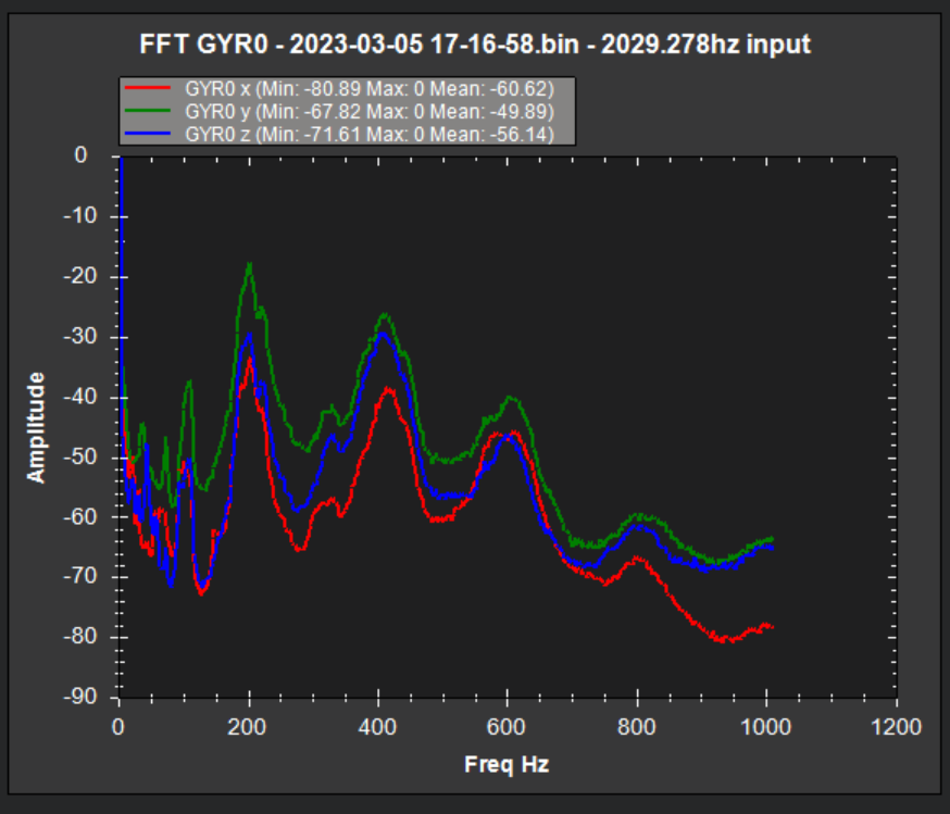
Worth noting that I did incorporate an notch filter (targeting 100 Hz cutoff freq), but it does not appear to be eliminating the 200 Hz mode. So this may also be contributing.
You have default parameters so way out over your skis running auto tune. The notch filter isn’t configured correctly either so at this point disable it and disable FFT. You have it configured for ESC Telemetry and you don’t have that.
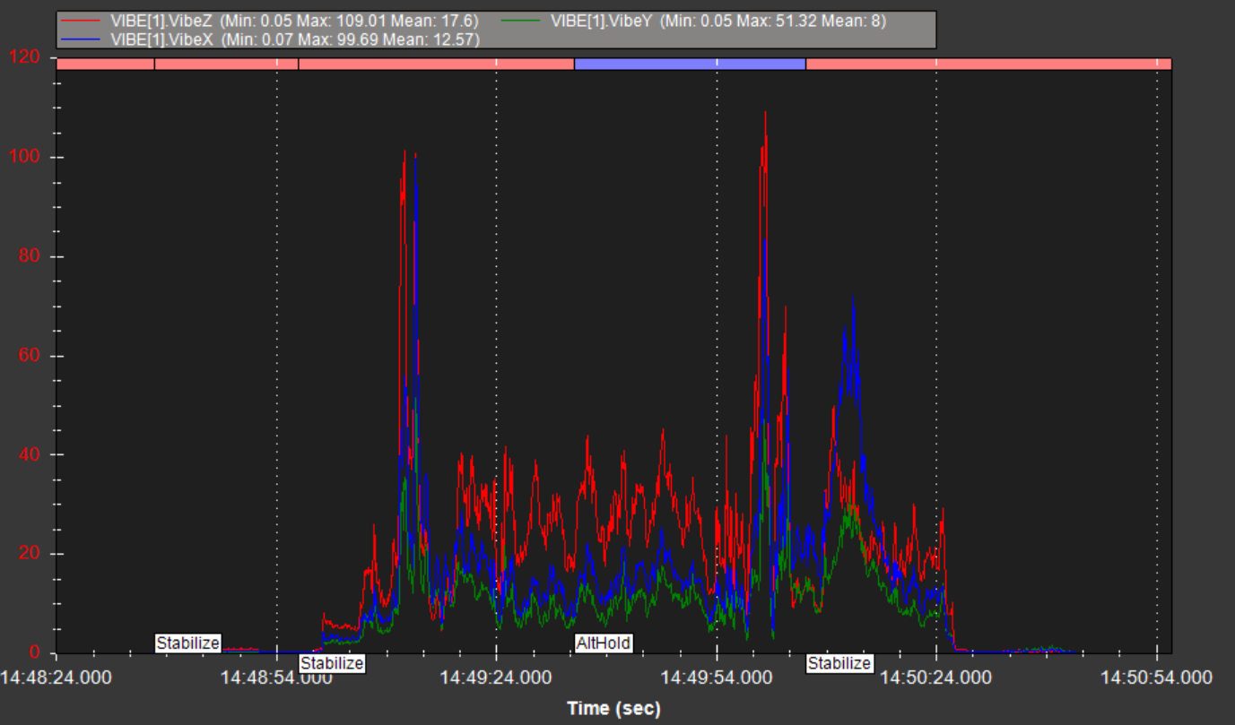
Start with the Initial Setup Parameters in Mission Planners Mandatory hardware. These are pre-1st flight settings. Then configure the Notch filter correctly for either throttle based or FFT (I would use throttle) based notch. Unless you actually do have Dshot capable ESC’s then configure for that. And set this:
INS_ACCEL_FILTER,10
Also, your X-vibes are high. This will make tuning more difficult.
Hey Dave appreciate the correction on the notch filter setup.
Wanted to clarify that I did run thru all of the Mandatory initial hardware set up here Mandatory Hardware Configuration — Copter documentation. Is there something that you’re seeing in the data that would suggest I skipped over something? Can you clarify what I’m missing here?
I also ran thru 2 initial tuning flights (stabilize and alt hold) and observed no ‘visual’ oscillations.So no changes to the default PIDs were made (as instructed in the wiki, if no oscillations observed)
At the bottom of this page under “mission planner helper” are the settings @dkemxr is referring to. Follow those instructions before you do any flying. They were not easy to find and I believe if they are going to constantly refer to this setup it needs to not be hidden in another section of the wiki and should be front and center. I will admit some sections of the wiki are a but clunky and the flow is a bit off. Also you may want to check your transmitter trims are centered and do a radio calibration I had this same issue trying to autotune a quad and making sure trims were centered and a radio cal helped.
“Failing to level” isn’t always visually evident. In my experience, it’s most often the yaw controller working too hard, which isn’t necessarily visually observable, but can be evident in the logs or even increased hover current and motor heat as a result of the rapid overshoots.
If it’s failing to level in the axis currently being tuned, it’s possible that it will just sort itself out. That’s unlikely and probably shouldn’t be the expectation, though I had it happen once where the initial roll terms were a little too aggressive, and autotune compensated somewhat quickly.
Another possible cause is vibration. Too much vibration will cause any tune to fail. Conversely, too much damping on the autopilot mount can cause incongruent acceleration measurements that are impossible to tune (and hard to diagnose, since the logs won’t necessarily show it clearly).
In any case, the already stated advice should move the goalposts a bit closer for you.
All of them from what I can see. These are default:
ATC_ACCEL_P_MAX,110000
ATC_ACCEL_R_MAX,110000
ATC_ACCEL_Y_MAX,27000
All the ATC Rate Filter values
INS_GYRO_FILTER,20
MOT_BAT_VOLT_MAX,0
MOT_BAT_VOLT_MIN,0
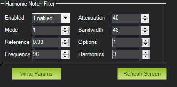
Thanks, @dkemxr. I incorporated the recommended tuning settings based on by 10" prop and battery. I attempted another set of hovers with the harmonic notch filter settings below, but am not seeing much attenuation. Is there anything else I’m missing?
Note that I set INS_HNTCH_OPTS = 1 to enable dynamic harmonic and INS_HNTCH_REF = 0.33 based on the recommendation in the wiki to set this equal to mot_thst_hover.
Almost, You missed these (still at default):
ATC_ACCEL_P_MAX
ATC_ACCEL_R_MAX
Disable FFT you are not using it (FFT_ENABLE,0)
The pre-filter FFT graph looks pretty messy but the settings you are using are working OK. INS_HNTCH_OPTS = 1 is not Dynamic Harmonic it’s Double Notch. Set this to 0.
Also set INS_HNTCH_FM_RAT,.75 to pick up some noise below the center frequency.
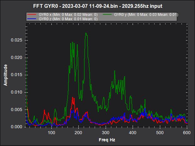
This is how it looks now pre and post filter. Clearly it’s working:
Pre:
Post:
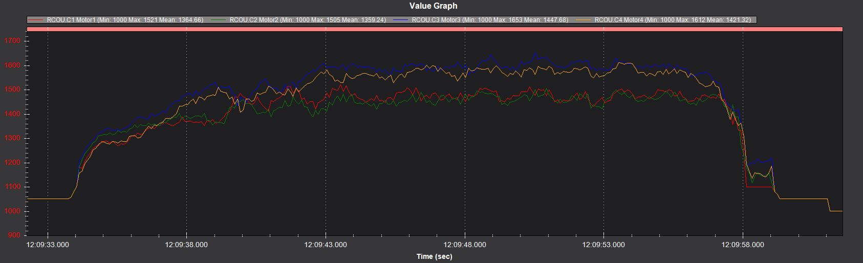
You have a bit of mechanical yaw bias. Usually because the motor mounts or arms are twisted a bit and all the props are not level. It’s not terrible but worth a look.
That is convenient - I did not use that - I manually updated in the full parameter list. I see that the autogenerated values for 10" prop are slightly different than those recommended in the wiki. Will go ahead and use the autogenerated ones
Yes and in your case it probably wouldn’t make any difference. But it’s the right tool to use. Auto Tune will change those parameters, this is just a good baseline.
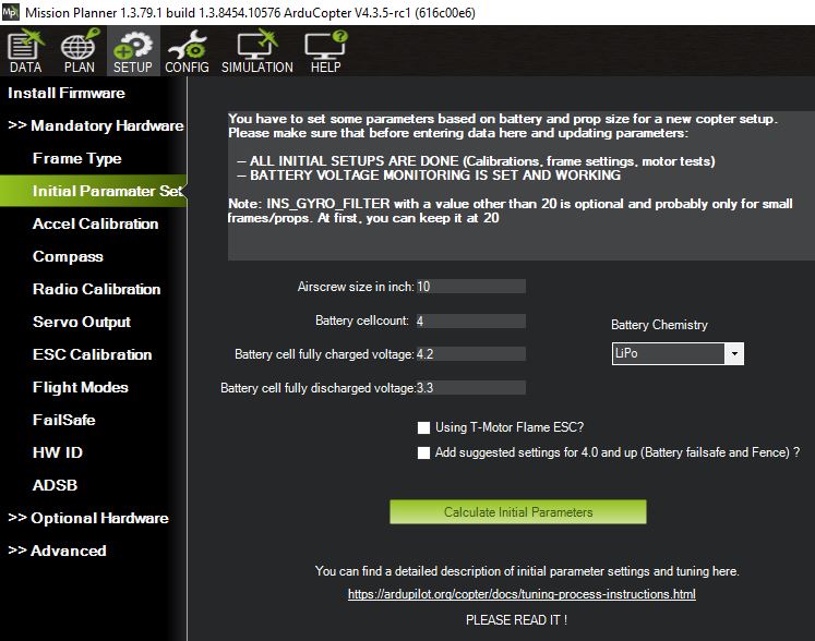
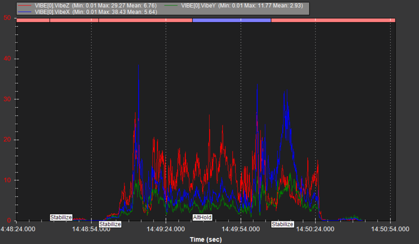
Did a quick flight in stabilize with a few stick inputs. Vibe on IMU1 is quite higher than IMU0 (see below). I’ve added some mechanical damping with gel pads, but am having trouble getting this lower.
Do you see any issue with changing EK3_IMU_MASK from 3 to 1 (use 1st IMU instead of both) to make sure the increased vibe detected on the 2nd IMU doesn’t cause navigation issues?
Obv there will be less redundancy, but high vibe may be a higher risk than reduced sensor redundancy.
No lane switching messages and raw accel gyro data is tracking closely between each IMU - So seems ok on that front. Definitely seeing some vibe clipping though
Vibes must be bad for an IMU isolated FC to experience this. You will struggle to get a really good tune w/o reducing them. What’s this craft look like?
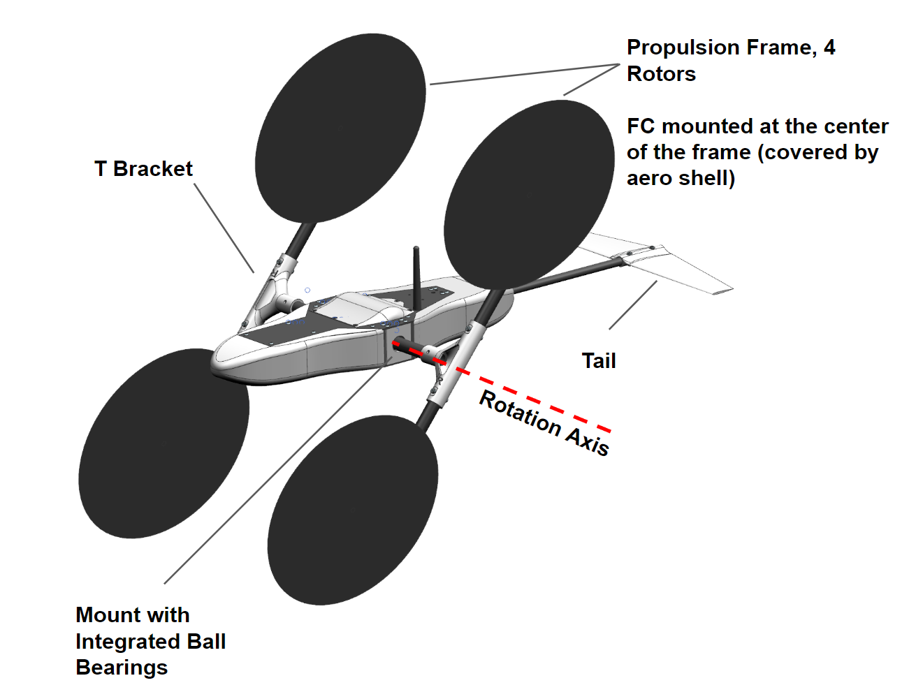
A new configuration I’m looking into to where the copter centerbody rotates independently from the propulsion system in the pitch axis and passively orients itself parallel to the freestream flow at all forward flight speeds (i.e pitch angles) to reduce drag. The centerbody is streamlined and features a tail so that aero forces produce a favorable toque that keeps it aligned to the freestream flow.
Rotation is achieved by attaching the prop frame (carbon fiber tubes) via bearings which are rigidly mounted to the center body CG. The ball bearings are preloaded within their housings to eliminate any radial or axial play - so it’s basically constrained to 1 DOF (pitch axis). These feel solid, so unlikely a main contributor to vibe.
I suspect that I need to make the T-brackets that join the carbon tubes stiffer, as I can feel some flex to them when I apply lateral force to the motor arms, which can definitely be contributing to the vibe. They are currently 3D printed polycarbonate, but looking into some stiffer carbon fiber filaments.
Inertia of the center body as the copter pitches could also be contributing to the higher vibe. The spikes in vibe correlate with sudden reverses in pitch (flying forward, stopping and flying back in revsere).