I’ve been frustrated a time or two on multirotor builds when attempting to decipher ArduPilot’s motor numbering scheme, so I created a couple of infographics that will hopefully help others avoid confusion when wiring their own Copters.
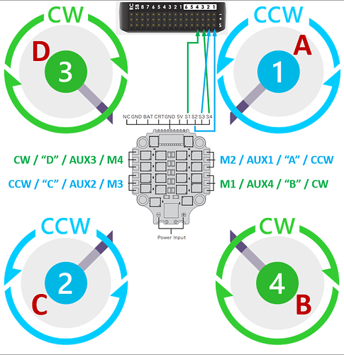
Refer to the following graphic for the example that follows:
ASSUMPTIONS:
I have a 4-in-1 ESC depicted, which is impossible to orient such that ESC motor numbering conveniently aligns with ArduPilot’s output scheme. To keep the wiring tidy, we will assume that each set of ESC pads is wired to the nearest motor on the respective “corner” of the frame. We will also assume an autopilot that requires this ESC’s protocol to be connected on the “AUX” ports (as in BlHeli_32, DSHOT, and most H743-based autopilots).
WIRING:
While wiring, ignore the motor letters - they are only really useful when using Mission Planner’s “Motor Test” function as verification that you have things connected correctly.
Starting in the upper right of the graphic, we can see that the ESC pads labeled “M2” are closest to ArduPilot’s “Motor 1.” Therefore, when wiring, we should connect the ESC’s “S2” wire to “AUX1” on the autopilot.
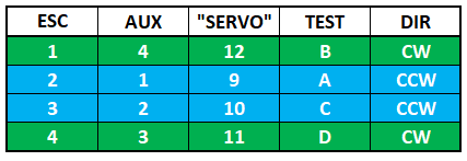
Unfortunately, there is one more complication: most autopilots of this variety refer to AUX1 through AUX6 as SERVO9 through SERVO14 in the parameters, adding a bit of fuel to the helmet fire we’ve already created. It may help to create a matrix like this for reference during the build and wiring:

Connect the remaining motors similarly.
TESTING:
To verify the wiring is correct, we can use Mission Planner’s “Motor Test” page, which makes use of letter order vs any numbering.
REVERSING A MOTOR:
Let’s assume that while testing, you discovered motor C needs reversing. With BlHeli_32 ESCs, this can be accomplished one of three ways:
So long as the numbering scheme is understood, the easiest method is via the SERVO_BLH_RVMASK parameter. Motor C corresponds to AUX2, and therefore servo/channel 10 in the example. In Mission Planner, put a checkmark next to “Channel 10” in the SERVO_BLH_RVMASK parameter (setting bit 9 of the mask, corresponding to a raw value of 512). Be sure to set SERVO_DSHOT_ESC appropriately when reversing motors with this bitmask.
Alternatively, use the BlHeli_32 configuration software of choice and a passthrough connection to reverse ESC motor number 3.
Lastly, you can swap any two motor wires connected to the corresponding pads on the ESC, requiring further soldering, which is probably ill-advised, as multiple attempts at de-soldering and re-soldering pads on a printed circuit board can result in damage.

