Is there some alternative version of the flight controller in the Cube family that has all the features of cube orange but without internal dampening
In multiple systems of ours, the vibration on the 3rd IMU is much lower than the 1st and 2nd, so it seems that the natural frequency of the internal dampening system matches the vibration frequency of the system. Is there a way to remove dampening by disassembly?
It is also very rarely an actual issue especially when you look at the log in replay quality and the waterfall fft.
It’s a topic that Paul and I discuss on a regular basis about how people are failing to understand the concept of isolation and the redundant nature of the Cube / EKF’s to manage the full spectrum of potential issues during flight.
I think the biggest change of late is the improvement to the imu3… what previously would have caused clipping in IMU3 is very well measurable… hence giving much better results overall… the cube Orange plus BG will be even better on imu3 than ever before.
In answer to your question, yes we offer a second foam option. Specific OEMs use it in some aircraft and it basically stiffens the foam to the point it is mechanically isolated from major stress and temperature changes but no significant vibration isolation at all.
We only do this after verification of logs, and normally after they consult @Paul_Riseborough
I will note that a consult with Paul is not a cheap option, but if you’re serious about finding the right solution, it’s absolutely worth the money.
Hi @proficnc@xfacta
As we discussed in facebook regarding Cube orange+ mounting weather damper mount or hard mount.
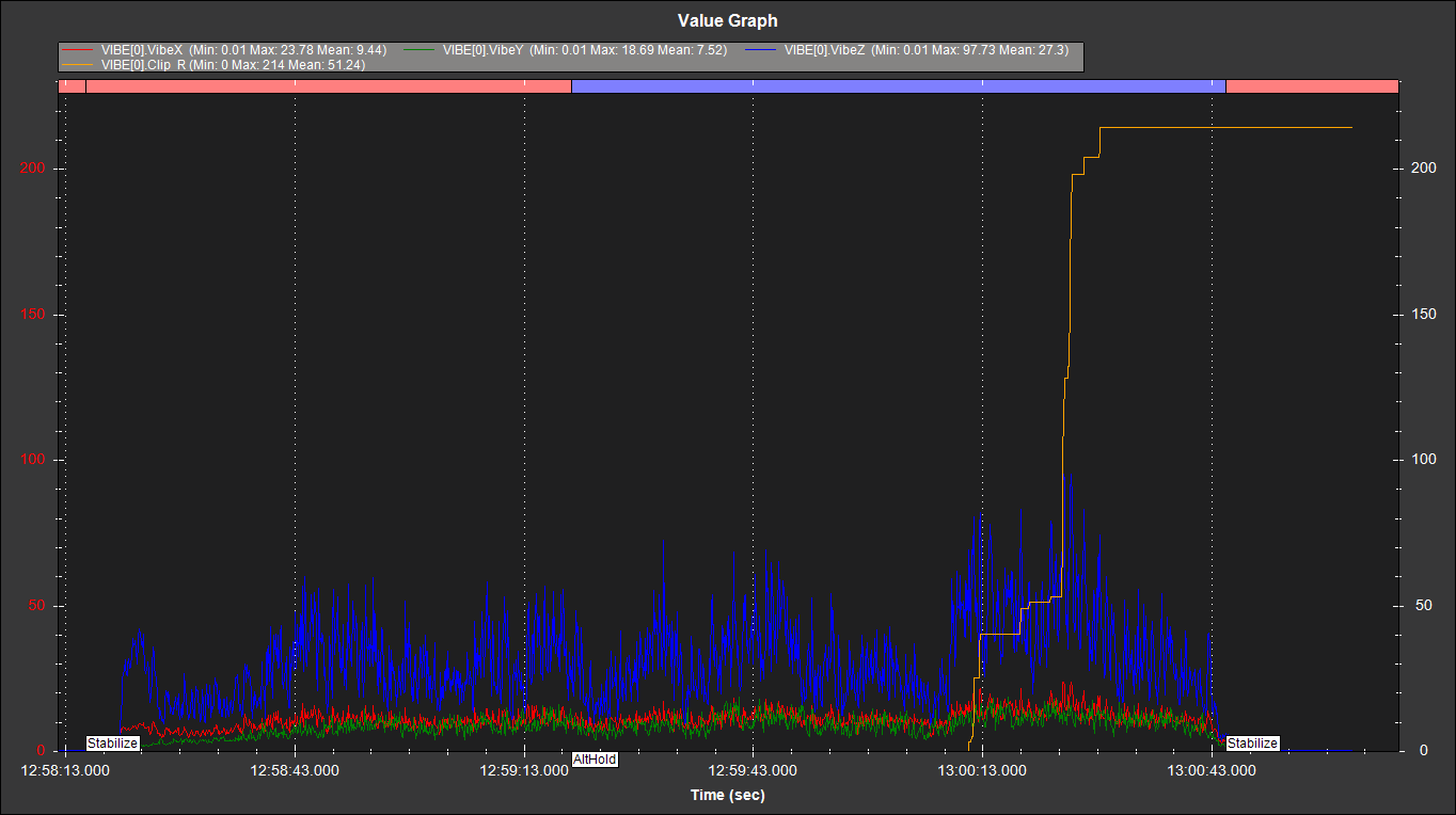
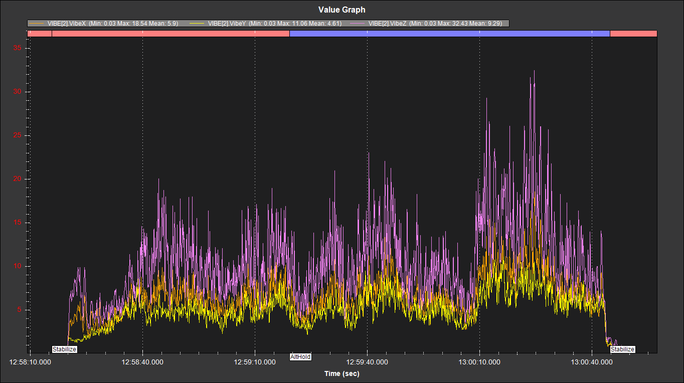
before i was mounted with rubber damper and getting more Z vibration on isolated IMUs compared to Non isolated Z axis vibration.
today hard mounted the CUBE orange+ with 3M tape given in the pack.
set parameter
INS_LOG_BAT_MASK = 1
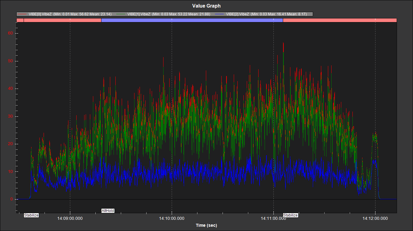
INS_LOG_BAT_OPT = 4 collected IMU data and Noticed that still isolated IMUs has same amount of vibration in Z direction and non isolated IMU has still less vibration compared to isolated IMU two.
here is the log and my Harmonic Notch filter configuration for collected data.
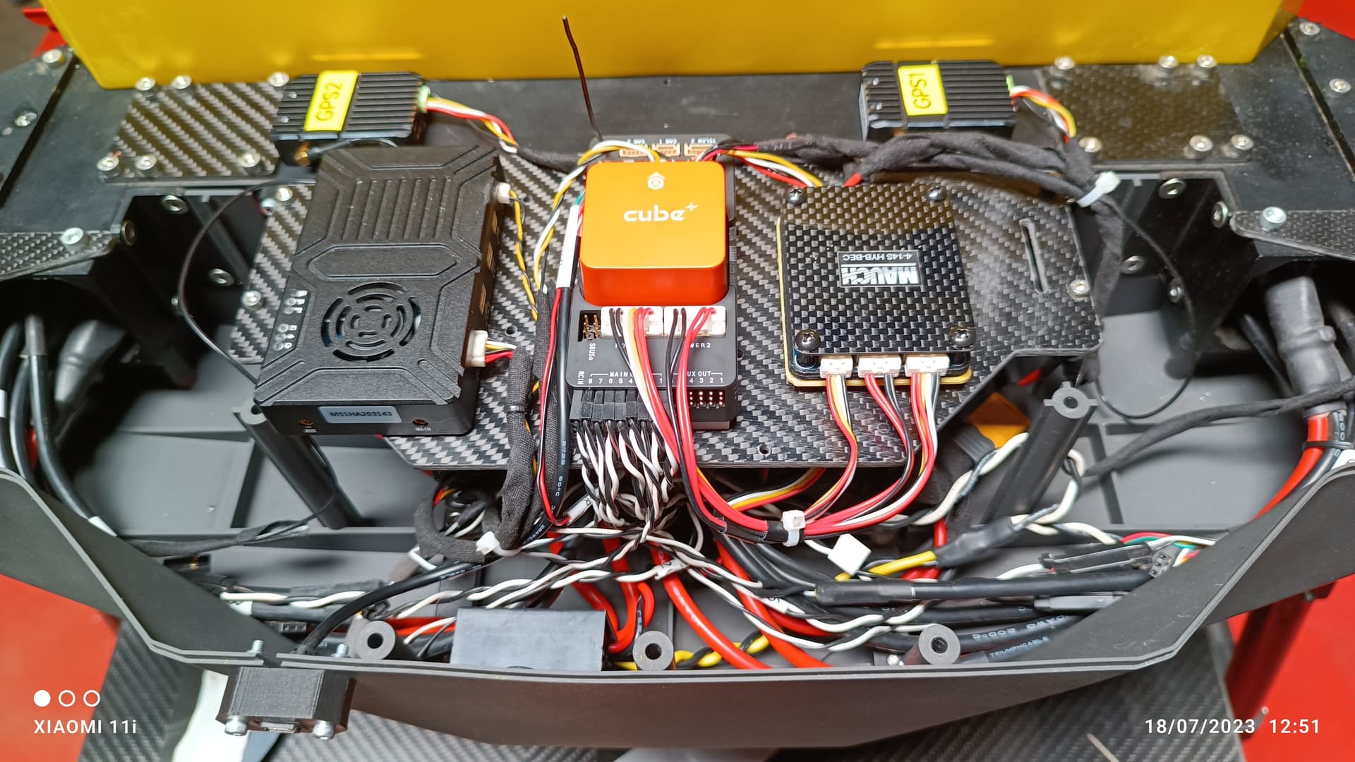
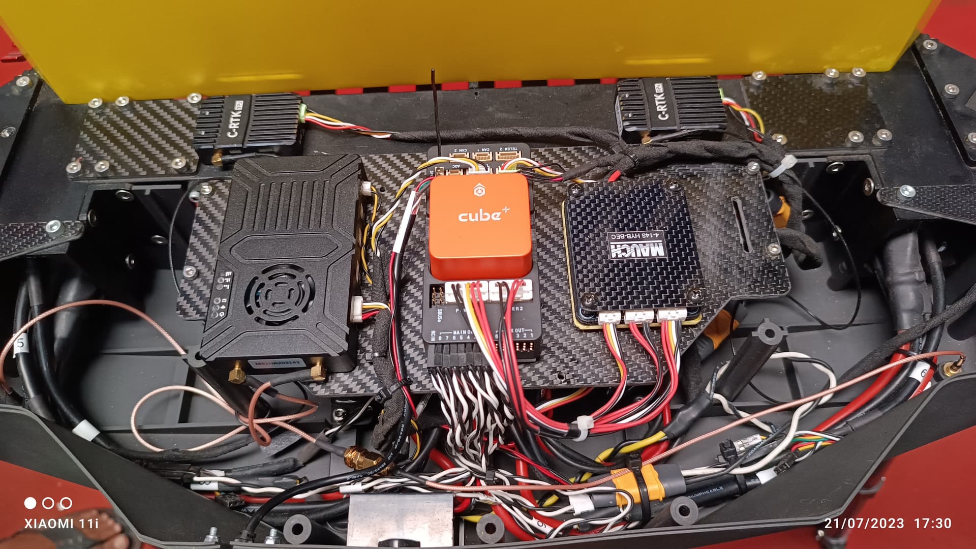
Without looking at the log, all of those look bad.
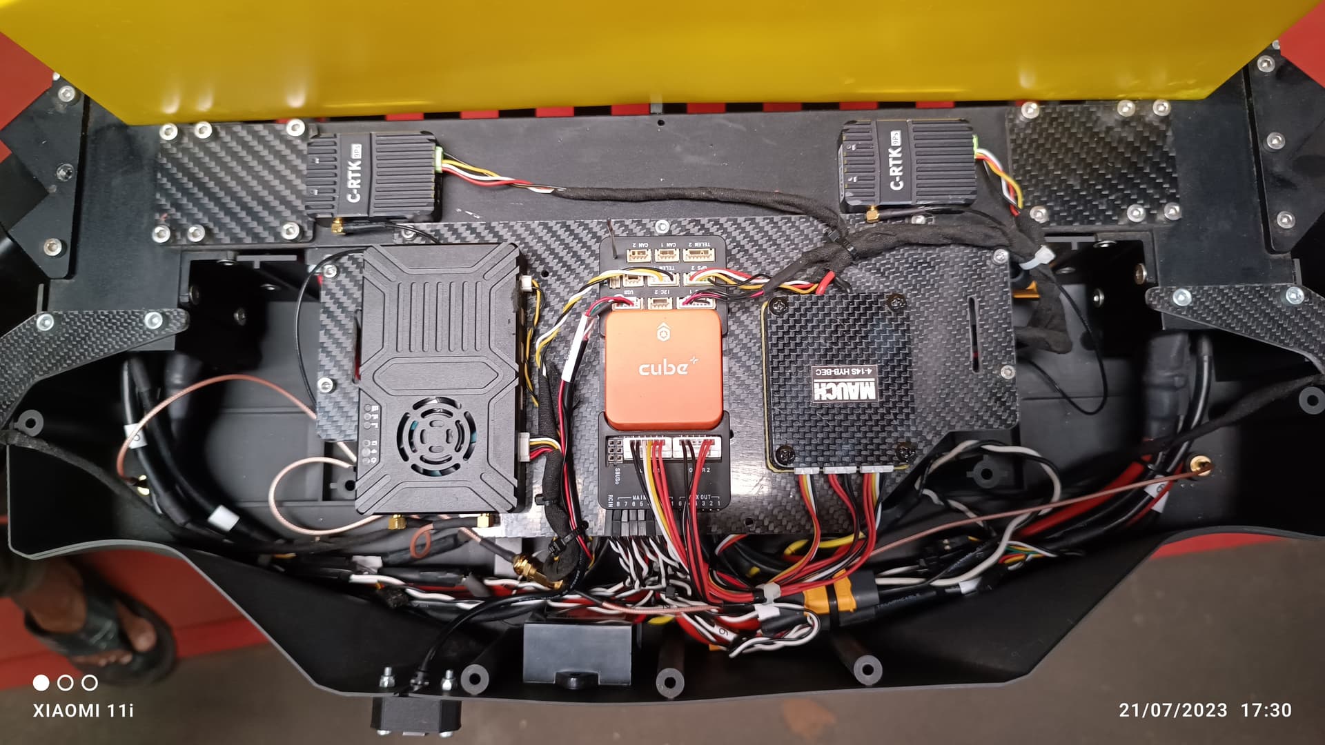
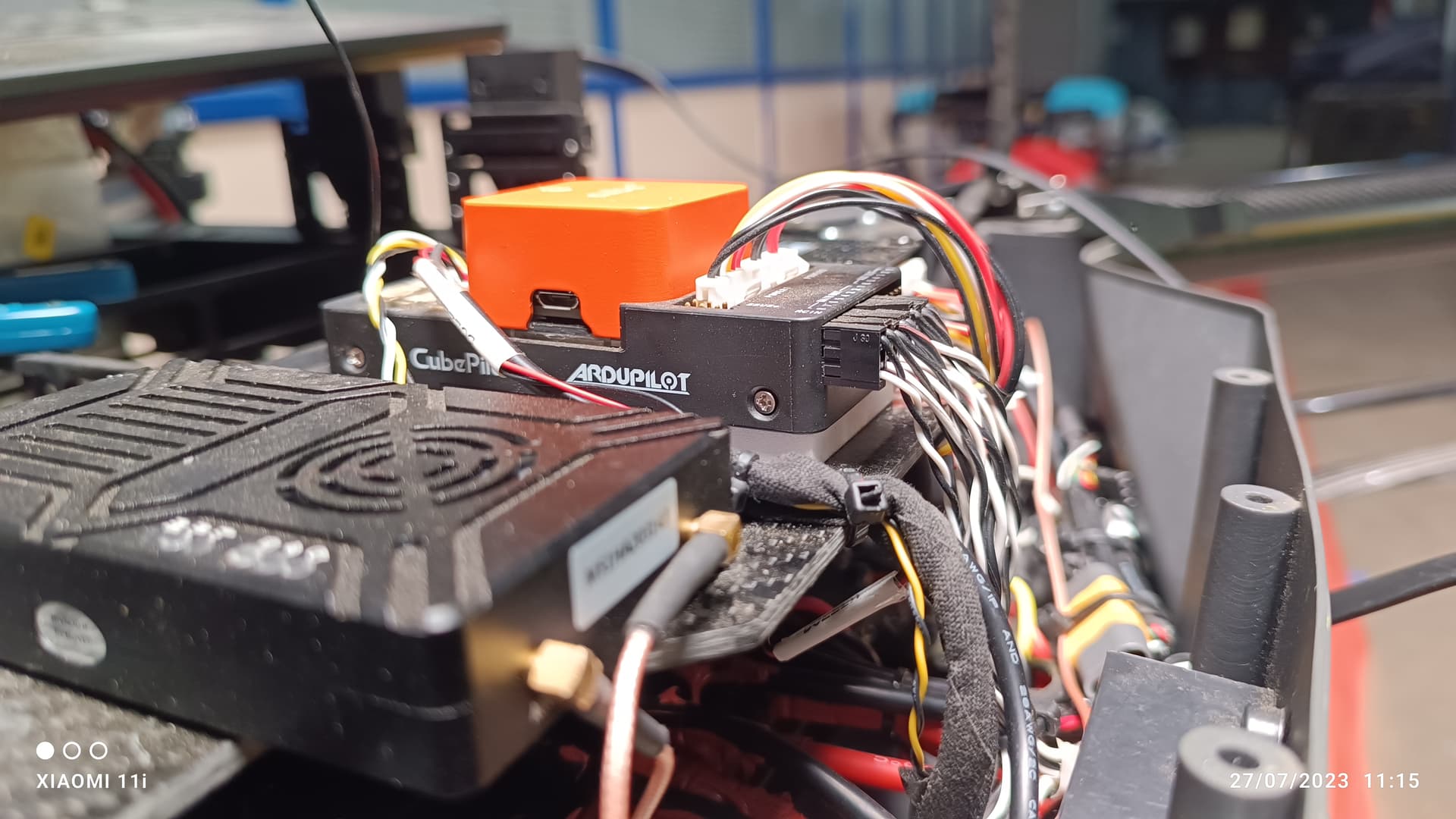
I’m suspicious of the wiring!
It needs to be secured to the platform, not hanging from the Cube and Mauch. The wiring will just be transferring and amplifying vibrations to the flight controller.
All the servo wires and ANY OTHERS all need that same treatment. The wiring connected to the FC needs to be flexible and not stiff and pulling against the flight controller (or carrier) but secured to the frame so the wiring is not putting weight on the FC.
Any wires that run along beside the FC or carrier board need to be NOT touching it.
And wires cant just be secured to other wires - they must all be secured to the frame at suitable points.
Any other wiring in the copter that is not secure should also be secured properly.
Battery cables and connectors have substantial weight and will cause vibrations.
I am very much sure and i have checked that all wires are not touching any part of the cube and mauch cables are also very soft only and its placed freely and not pushing or tension with cube…
All wires are very flexible only no stiff wiring on cube…i have checked.
But why non isolated IMU has very less vibration in all axis when compared to isolated IMUs?
I will try to reroute the cables as per your suggestion and can you check my Harmonic notch filter setting is correct?
Yes I can definitely help check these things.
Keep in mind the Harmonic Notch Filter is software and comes after fixing the physical vibration issues as measured in the logs with VIBE data.
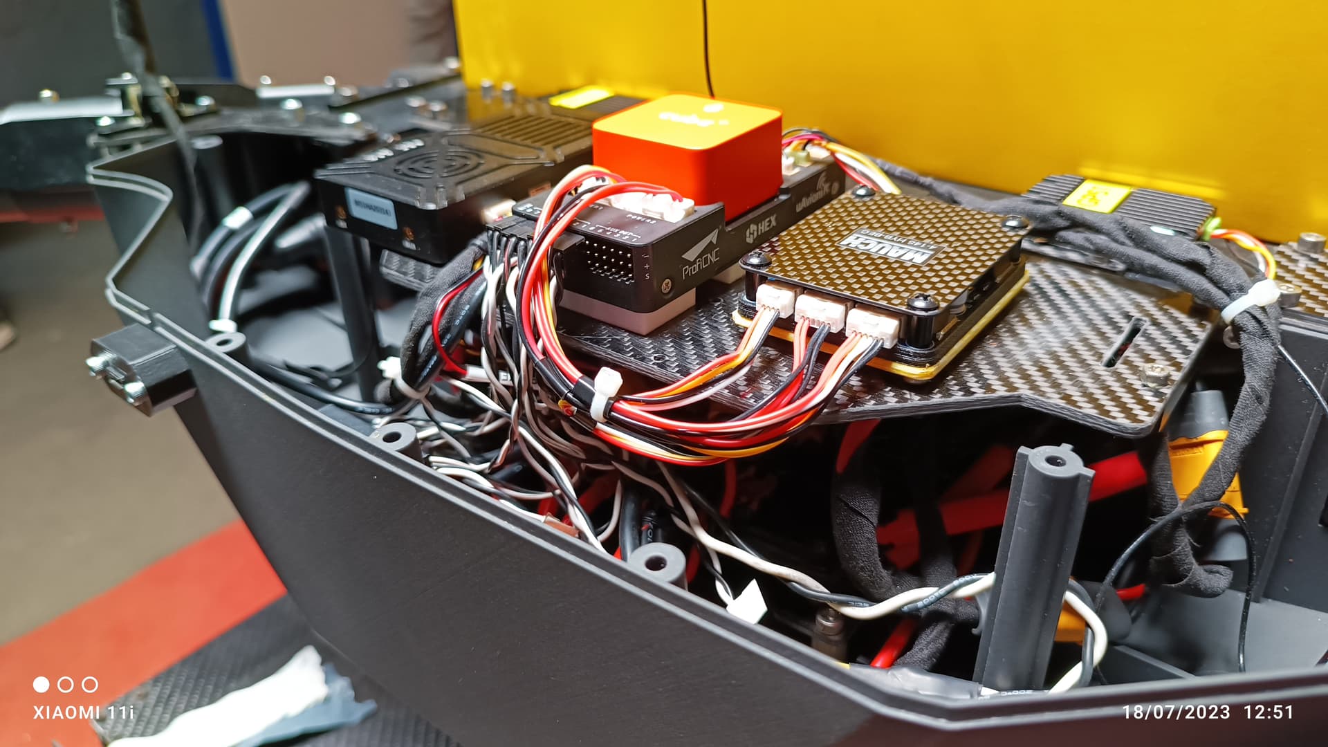
Your wire organization is very neat and tidy, but there are quite loose lengths near the carrier board that will contribute to (or cause) the issues observed.
Which wire you are indicating loose near cube carrier board USB port cable.even though if that wire either loose or it may pulling towards one side this must cause either X or Y axis vibration right.how come z vibration is getting higher even isolated IMUs.
I have checked propeller balance as well as foldable prop tightness on each propellers.
I have just rerouted the cables around the carrier board and now no wires touchs the carrier board including ESC signal wires and all cable has been tied up .
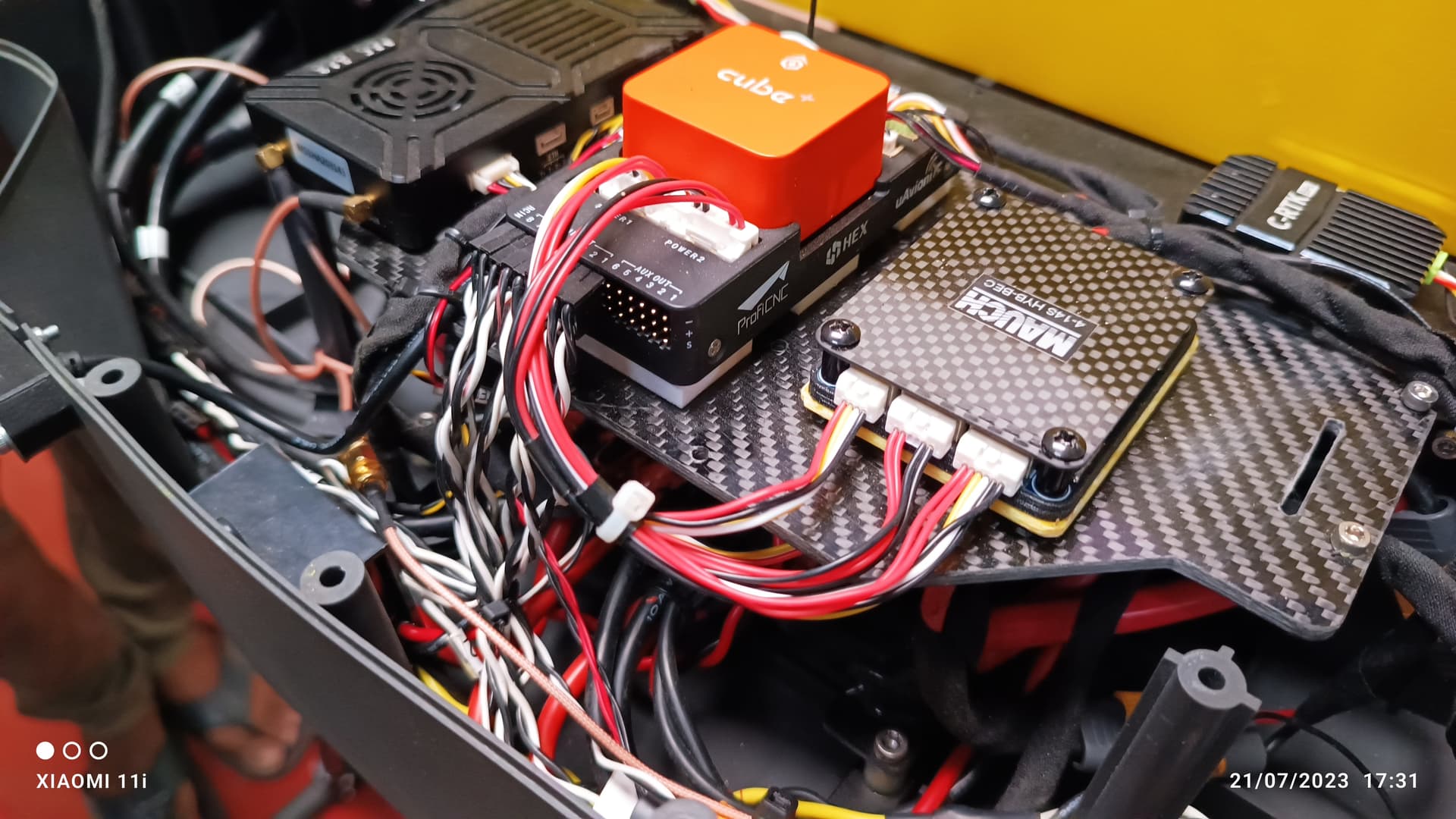
Still some long cables or bundles that could be tied down a bit more. I started circling them, but then I realized I was circling nearly every wire in view…
It’s OK to be neat and tidy, or even a bit messy, but everything has to be secured to the frame in a copter. Wires cable tied to other wires just means there is more mass to move around and vibrate. They need to be tied down to the frame, but with enough flexibility at the ends so they wont break at the connectors or transfer vibrations.
For example, those PowerA and PowerB wires between the Cube and Mauch - they need to be secured to the plate. Probably at their mid-point would be sufficient in this case. Otherwise they will vibrate and shift around and be like a lever amplifying their vibrations at the carrier board (and onto the Cube).
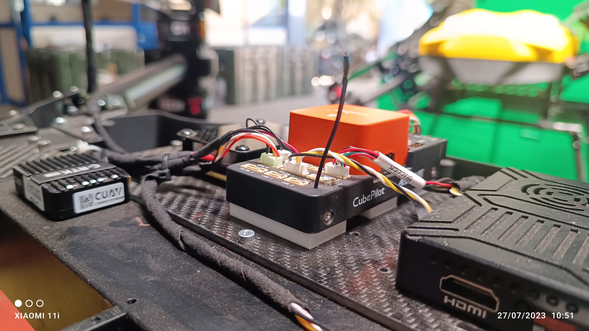
Here is an old copter of ours, it’s not a perfect example but you should be able to get what I mean.
You can see the GPS and Telem wiring are secured at the base plate (where I put an arrow) with enough free/flexible wire to allow freedom but not so much the wires need to be supported by the flight controller.
It’s not obvious in this picture, but the servo wires and power wires were also secured to the base plate.
Ignore the bits of grass and debris
Ignore the blue and black wires sticking up in the air, I think I had just added yaapu telemtry and I tidied up those wires later - they are certainly different now.
Hi @xfacta
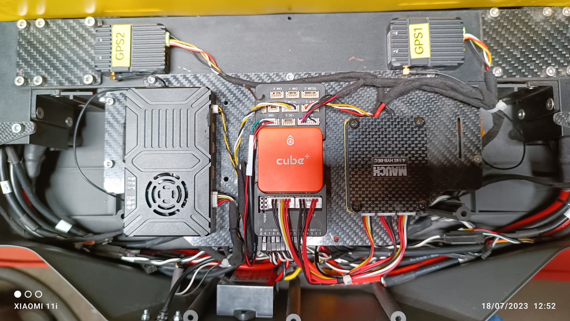
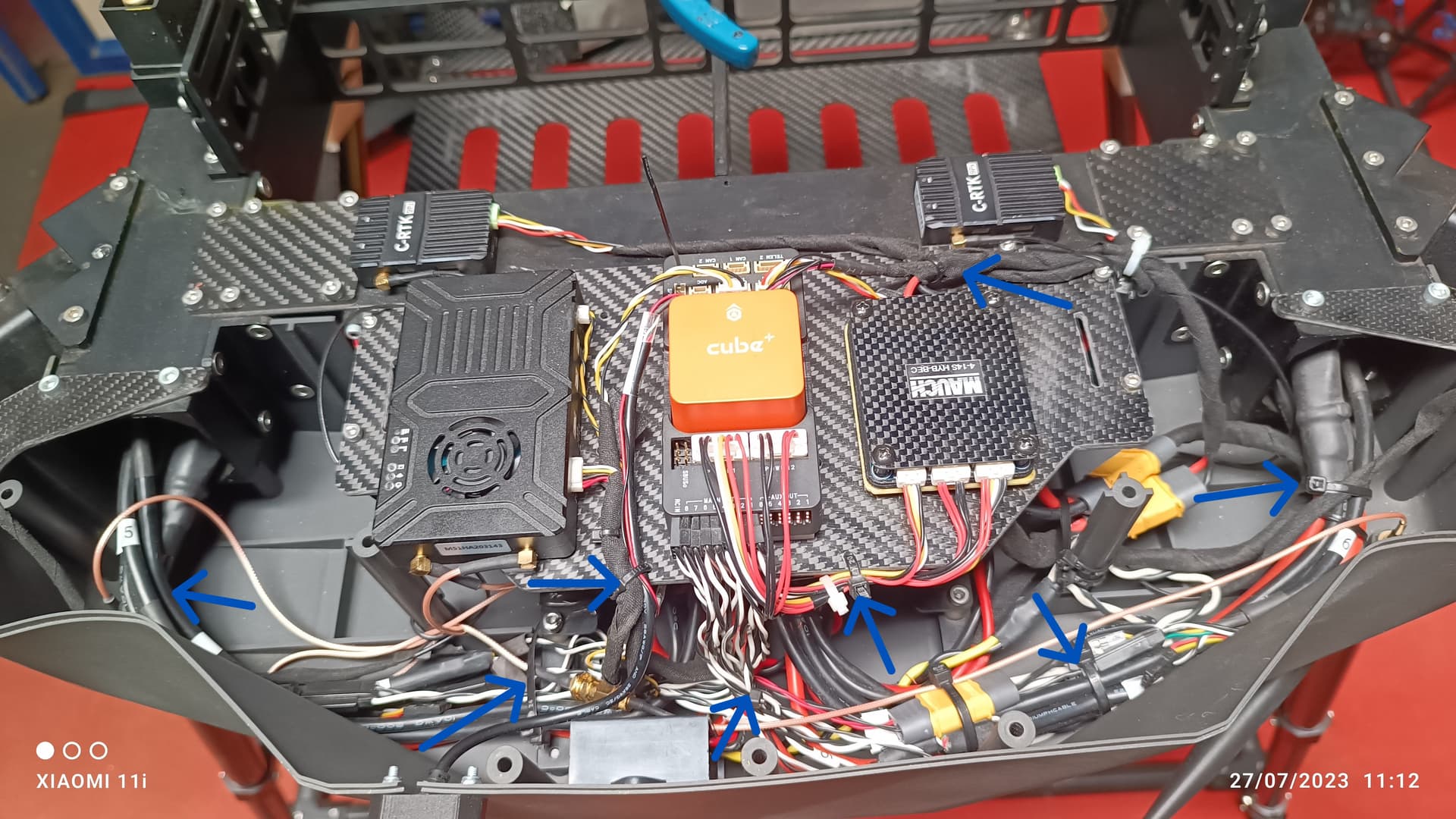
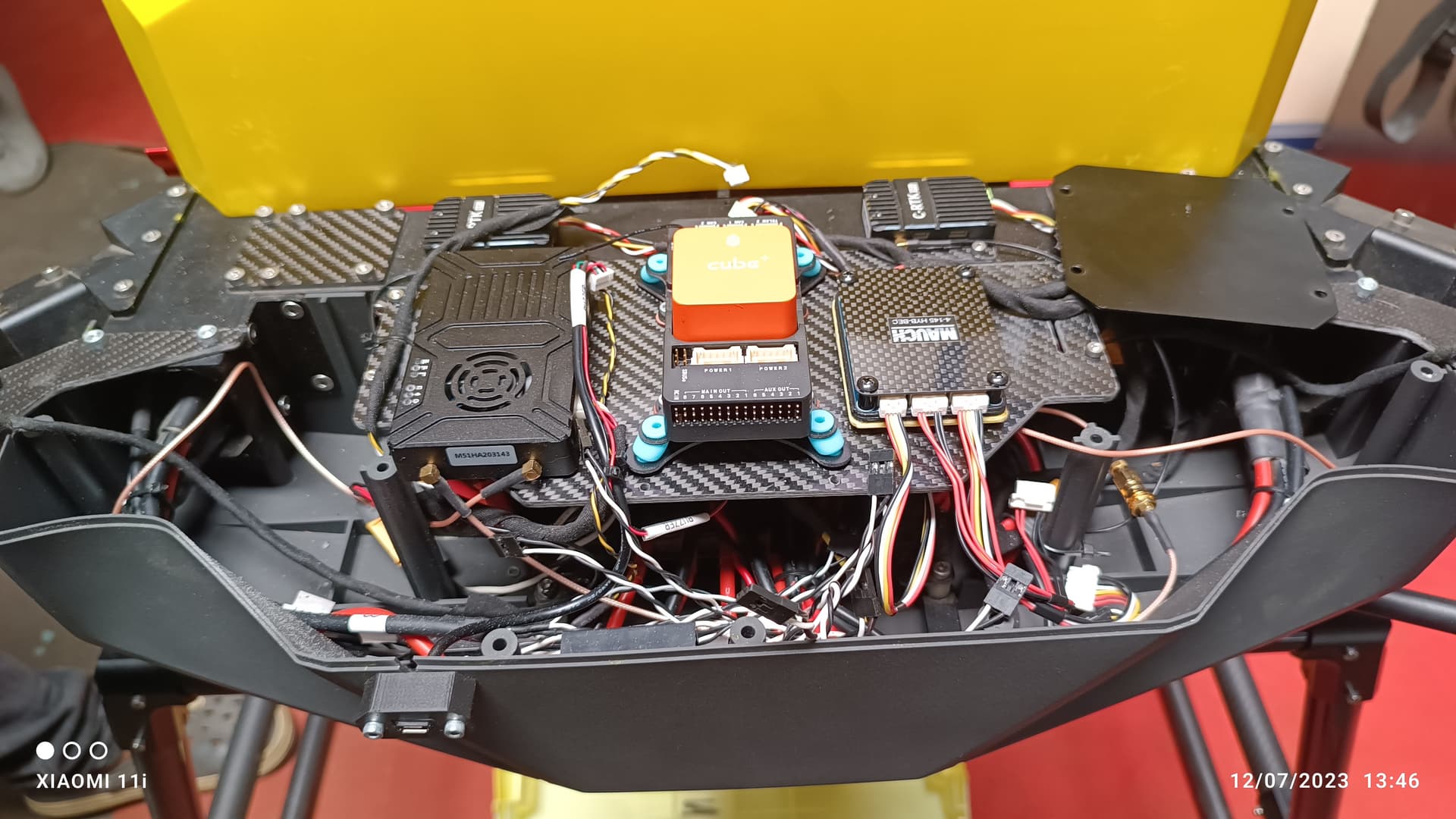
as per your suggestion i have made all cables tied up with frame body where ever is is possible and same images is attached here for your reference.
i just marked the tied point with frame where ever possible and no where pulling cable.
but still i had same issue that Z axis vibration peaking up badly on isolated IMUs. but NOT on Non isolated IMU.
there is not such vibration on X and Y axis as i already told .propeller balance also checked.
here is the log for yesterday test flight.
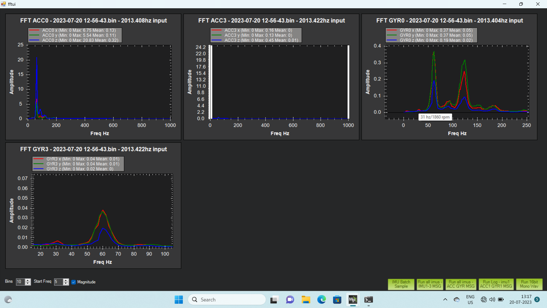
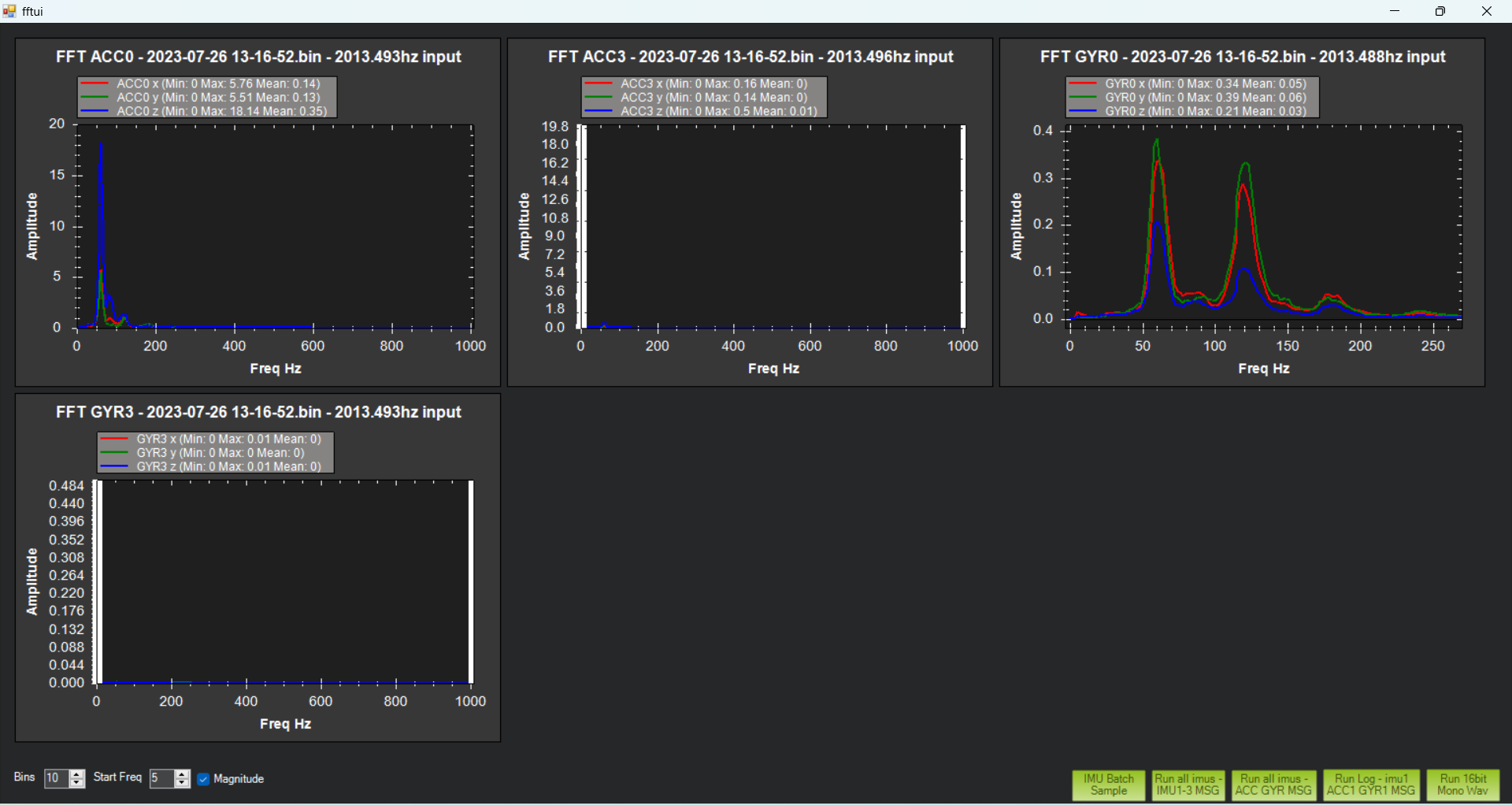
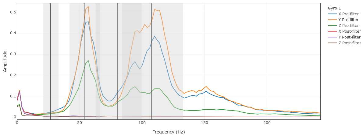
the above log is to collect FFT data
i have got peaking around at 60hz
but as per previous flight log which posted earlier on this topic here it was shows there was small amplitude at 30Hz so based on that FFT data i have configured harmonic filter setting like this and performed this again yesterday. but yesterday was there is no peak amplitude at 30 and it started at 60hz.
here is the previous flight FFT graph and harmonic configuration.
still drone is under control to fly even though there is more vibration know this should not we try but want to know the flying behavior’s when there is excessive vibration. log for flying with excessive vibration.
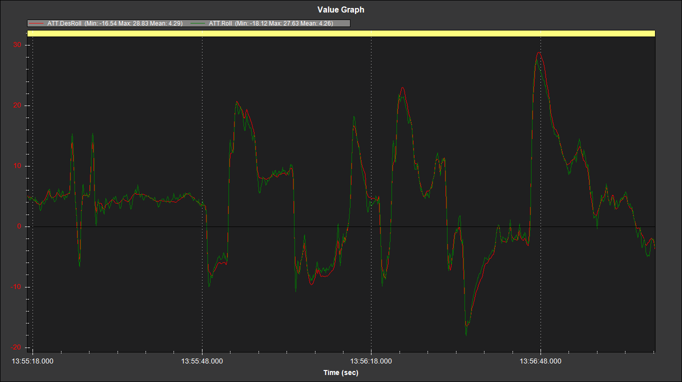
here is my attitude angle controll on ROLL and PITCH
Good work with the wiring.
It looks like there might be too much double-sided foam under the flight controller. Maybe that’s something to explore.
I see what you mean about the high Z vibrations. You will probably need some different flight controller mounting system, like that 3D printed one I referenced. There is clipping in the isolated IMUs so dont fly again until you are sure Z axis vibrations are improved, or you risk a fly-away. Clipping indicates vibrations have exceeded the physical limits of the IMUs.
The good news is attitude control is still very good for such a large copter.
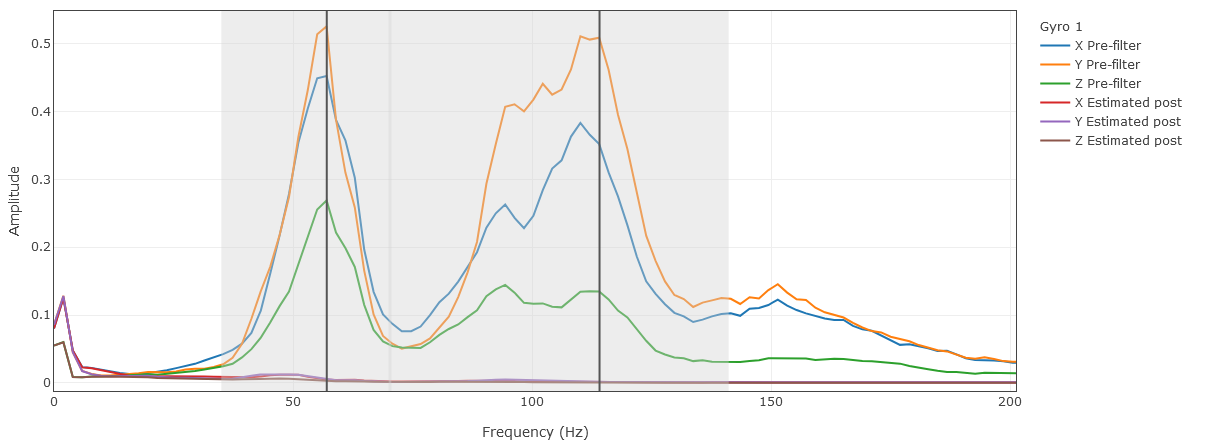
And the harmonic notch filter is working well at squashing the noise, even if it is a bit overkill with a lot of harmonics specified. I guess the wiring changes you made got rid of the 30Hz noise and we are left with the harmonics now, because 30Hz is still around what those props should do for hover.
Based on that log I would simplify and adjust it to:
Also I’m thinking Rate P&I values could be higher and D could be even lower based on the activity I see in that log. But I’d prefer to see the physical vibrations reduced a little further, the new filter settings go in, and a new test flight before changing any more PIDs.
EDIT:
MOT_THST_EXPO might be a bit high even for those props. If you did tests and that is what you calculated, that would be great (and I could save it as a datapoint in my MOT_THST_EXPO data collection)
However I suspect it should be more like: MOT_THST_EXPO,0.82
The filter was like this before my suggested updates. Lots of phase issues not shown in this graph too.
I took a look at your log and photos, and I think the gel pad may not be suitable for you.
I think you can try this, but be sure to pay attention to safety! Stop immediately if there are any problems! And this is just a suggestion, I think it might suit you. Your VIBE is ridiculously large and your gyro is a mess. If there is nothing to change in your frame or motor, or if someone else has successfully used your frame, I think you should focus on trying other external damping.
In my limited experience, only one large copter allowed me to stick the FC with built-in damping directly on it, and it had huge 68-inch props. And after the RPM increased, the vibration became unacceptable.
If you use 3D printing, be sure to pay attention to the temperature! Remember!
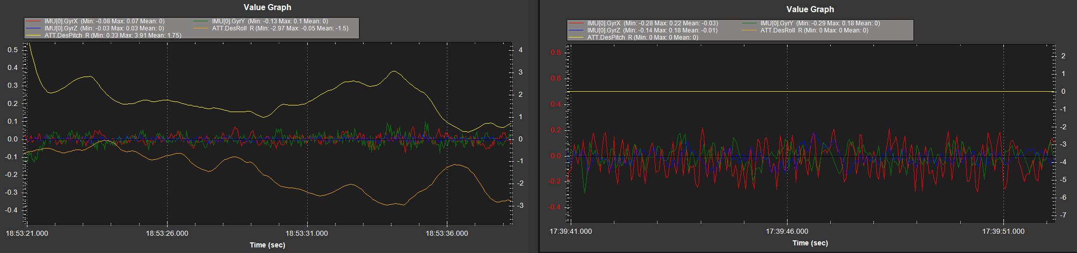
This is the effect of my friend using this shock absorption platform. I didn’t test it directly, but I also recommended the same thing to my friend.
My friend used 6 22-inch T-motor kits.
In the picture, the log on the left is after using the shock absorption platform.
its came up with cube orange+ flight controller itself and also it has small size foam tape also you are recommend to use that instead of this bigger one?
infact i have stared mount the cube orange+ with rubber damper only and had flight too. but same Z-axis vibration was huge. but satisfied thing was with damper i don’t see the clipping.
After this flight only i have requested help to Philip Rowse and he strongly recommended NOT to use these kind of Rubber damper and it must be hard mount and see.
so as of now you suggest to keep the current harmonic filter setting until clear the vibration issue. after vibration issue cleared your harmonic filter setting has to replace?
i will try any other method to try reduce the vibration and let continue the testing.
This MOT_THST_EXPO is based on initial parameter result by the mission planner based on the Propeller size and Batt voltage.
thank you for your support @Ben_bili
i have already working on frame side to improve what are the source of vibration that can be minimize.
and stared working on this anti vibration mount on 3D print.
i wonder if 3D print will not get broken from continuous frame generated vibration. you have any recommendation for the 3D print thickness.
As i replied to the @xfacta Philip Rowse who manufacture of Cube pilot who strongly recommended not to use rubber damper for this FC.
I’m sorry, my friend used PA-CF as the material and used 0.2mm as the layer height. I don’t think his reference value is great, as PA is a difficult material to 3D print. If possible, I think it would be more appropriate for you to use CNC parts, although they are very expensive.
What I hope is that you pay more attention to the temperature of the environment, as PLA will soften at 50°C. If you are concerned about strength issues, you can consider setting a larger fill rate and wall thickness for it.
I don’t think there should be any strength issues unless you plan to use it for a long time. In this case, I hope you will definitely use CNC parts.
The shock absorption platform you are using will cause the CG to be too high unless you install very heavy counterweights under the upper platform. I don’t know if this is why Philip Rowse reminded you, he may have a deeper understanding of these issues.
I would agree using that type of 3D printed mount has done a good job.
Your friend would be able to further reduce the vibration be removing that USB connection and finding a smaller more flexible USB connector. Search your favourite online stores for “micro usb flat cable flexible”
And paying more attention to the wiring, which all needs securing.