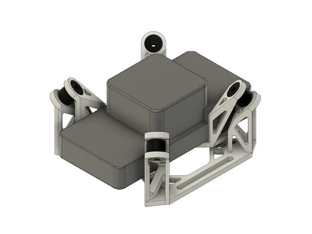
The sort of antivibration mount you have is very basic and OK for use on small cheap copters. I would avoid it even for basic usage. Where I have needed a basic antivibration mount I used a 3D printed version that angles the damper balls so they are not stressed (see in my earlier pic). Yours wont offer uniform damping in all directions. You can see the damper balls are already stretched.
Get that other mount 3D printed and try that, I’m sure it will be a lot better.
To allow for high ambient temperatures you could get the 3D printing done with ABS.
The official recommendation is to ALWAYS hard-mount the Cube and carrier but there are exceptions to that rule, and it is common to soft-mount the Cube and carrier in high vibration situations. Every case can be different, and there are exceptions to every rule. We have plenty of cases on these forums where a Cube needed antivibration mounting.
NO. Put in my recommended settings right away. They will do an equally good job of filtering noise but with less overhead. Once vibrations are under control we can re-assess the filtering and hopefully settle on something that can remain in place for ever.
Yes I understand. As more data has come through over the last few years, I would be very suspicious of going over 0.80 for MOT_THST_EXPO for any props. I’ve been refining the formula used in that calculation and that’s why I recommend MOT_THST_EXPO,0.82
since it is not a big change from what you have now, and also not far from a line of thinking that says we shouldn’t go over 0.80.
In the original Initial Parameters spreadsheet, that was converted to the plug-in in MissionPlanner, I used a formula to calculate MOT_THST_EXPO based on Leonard Halls experience and knowledge, and the formula gives an approximation of course. In reality different props may deviate from the formula. Some ESCs even affect the real outcome.
I’ve been working on a new formula that might be a little closer to correct in more cases, based on tests that have been occurring. The data is not complete yet, but I have enough to adjust the formula a bit and still produce reasonable results that are a closer match to actual tests.
Here is the link to the current spreadsheet. The new formula is used in the “4.0+” section and the old formula is still in the “3.6 and earlier” section as a reference.
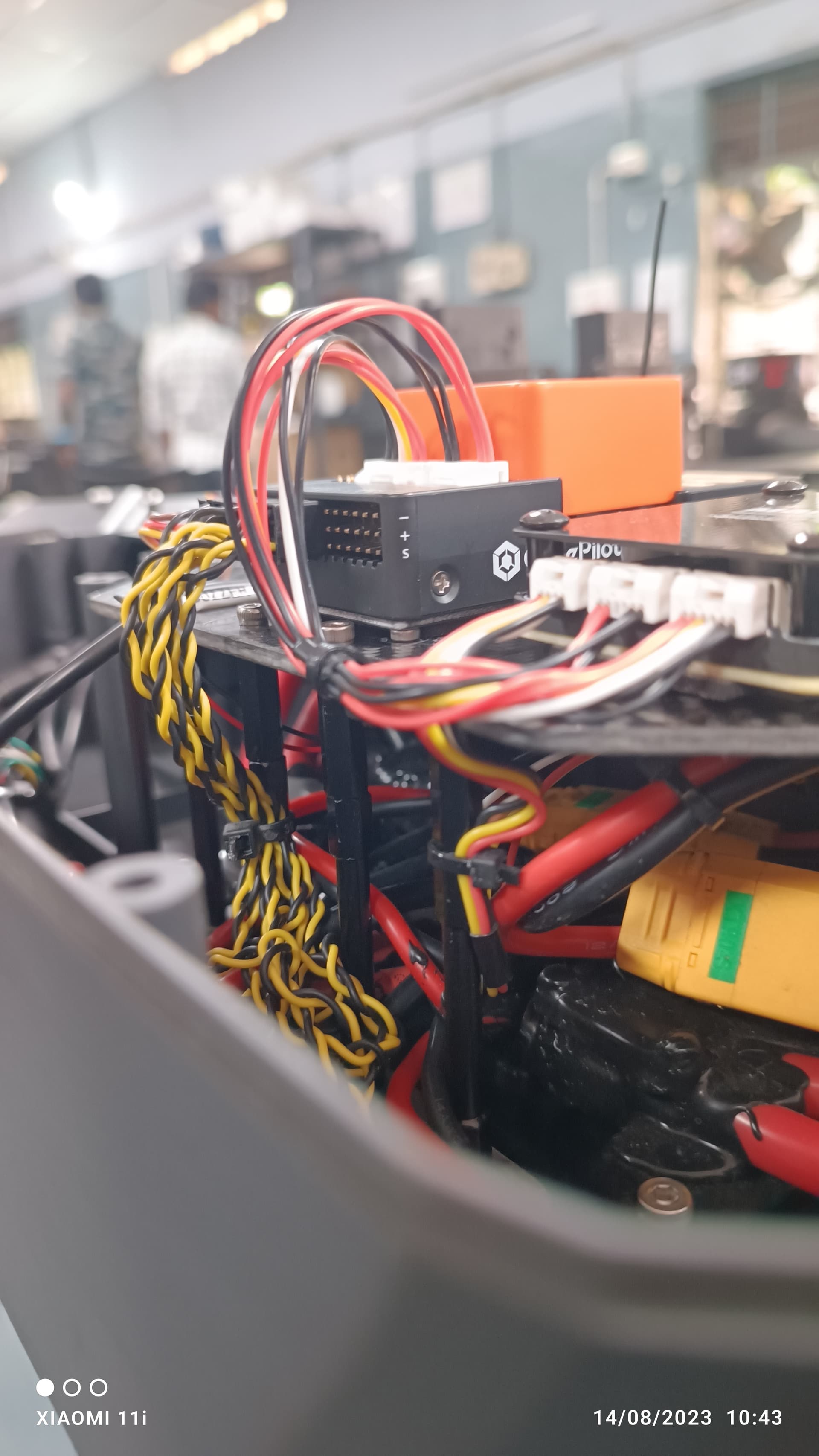
I did remind him to organize these cables, but he didn’t seem to take it to heart, and I think maybe it’s not time yet. That USB cable is only used for downloading logs, and it will be removed after the download is complete.
I think that for larger drones like this, any 3D printed shock absorption platform that is not made of PA or PETG should be avoided. PLA will have problems at high temperatures, and ABS is… I have tried ABS printing many times, and in the end I found that the 230°C given by many manufacturers is not suitable. After I raised the printing temperature to 270-280°C, the adhesion between layers improved a lot. I think the manufacturer may have provided us with the temperature used for injection molding, and the environment of 3D printing is very different from injection molding.
Such a high temperature without a warm air blower to provide a warm atmosphere, ABS will almost certainly warp. I have calibrated the temperature of my 3D printer with my multimeter. I think if it is not a 3D printer with a warm air blower, you should not try to print ABS and use it in places where high reliability is required.
If you try to print ABS at 230-250°C, it is likely to break easily.
Of course, a slower printing speed may be fine. My printing speed is usually between 30-50mm/s. Slowing down may improve this problem, but I don’t want to wait.
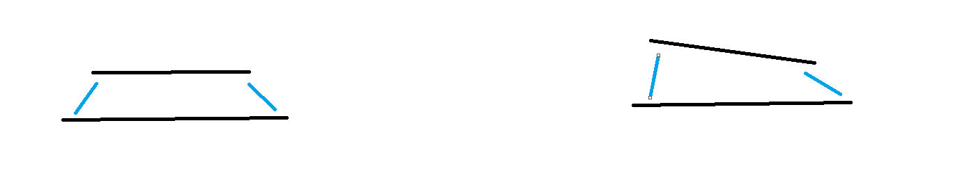
I’m worried that tilted dampers will cause this problem. The picture is a bit exaggerated, don’t mind too much. Of course this is just my guess, and I have no evidence that this problem will occur.
That’s true for every drones I made using Cube which had the propeller size larger than 28inch. For the mass production, I had to ask Hex to replace the “default” foam to the other one.
Hi @Ben_bili
As per above statement the sway will happen in lateral axis which is X and Y direction right. But in my case the main vibration happened in only Z- axis.
If added weight to the damper plate will arrest z axis vibration!
Oh no, you misunderstood me. What I meant by sway is rotation, the FC will rotate frequently around the CG as the center. You will definitely see crazy swinging curves in the gyro of the imulog, not swaying on acceleration.
Of course, increasing the weight of the counterweight can also compress the rubber ball to improve the shock absorption effect. You can try it, but all weights should not exceed 200g for four such blue rubber balls.
@xfacta sorry for taking long time here to update.
i have decided the to do same test on another new set of cube orange+ on different drone but similar type drone.
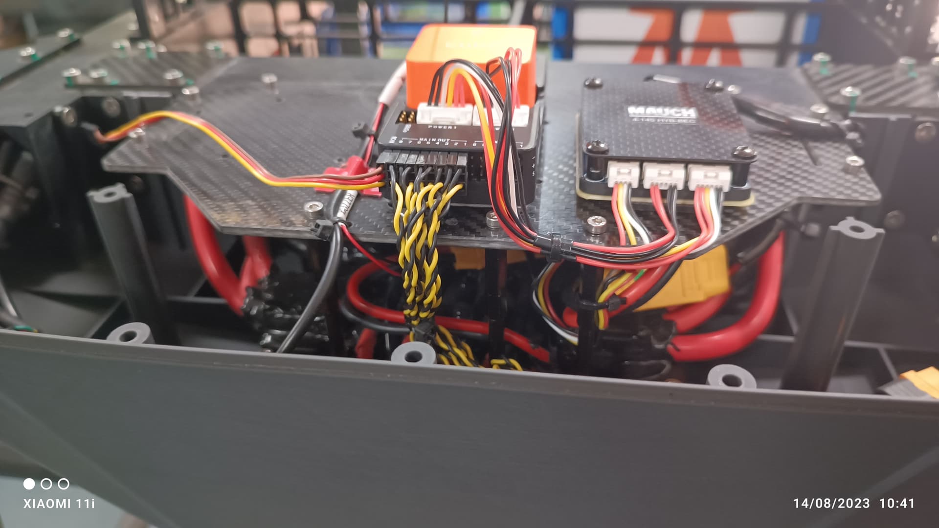
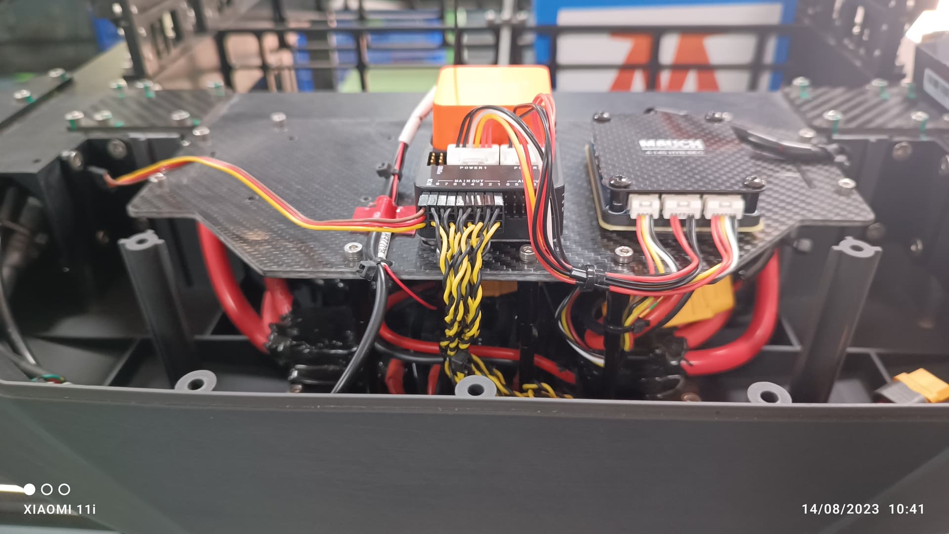
this time i have mounted with less thickness foam tape which come with cube orange+ boxes . Last time you mentioned the issue may be with large foam tape. Images attached below.
You can notice in the image i have added 4 spacers to stiff the autopilot carbon fiber plate with airframe. this i did not done this on previous airframe.
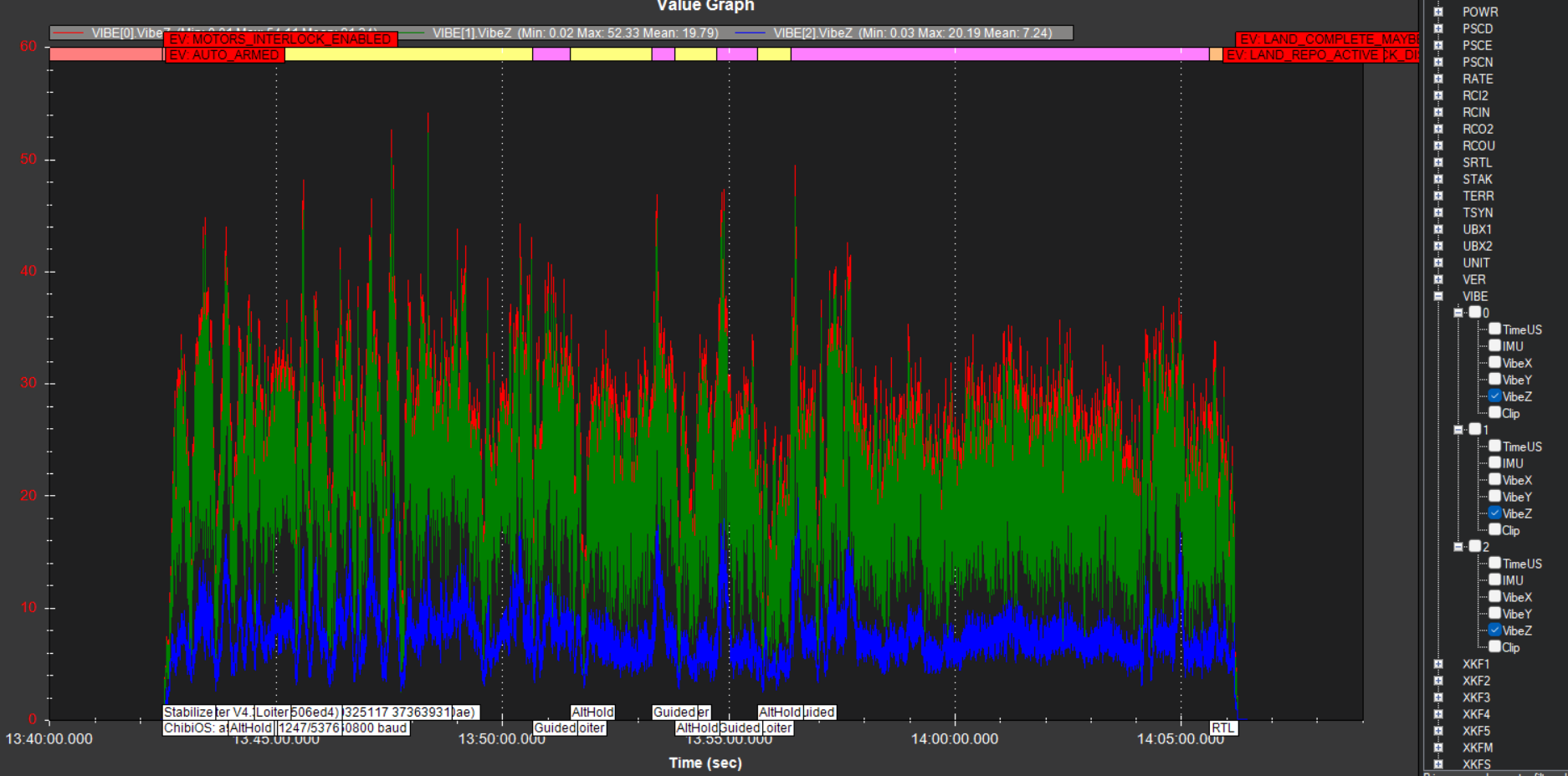
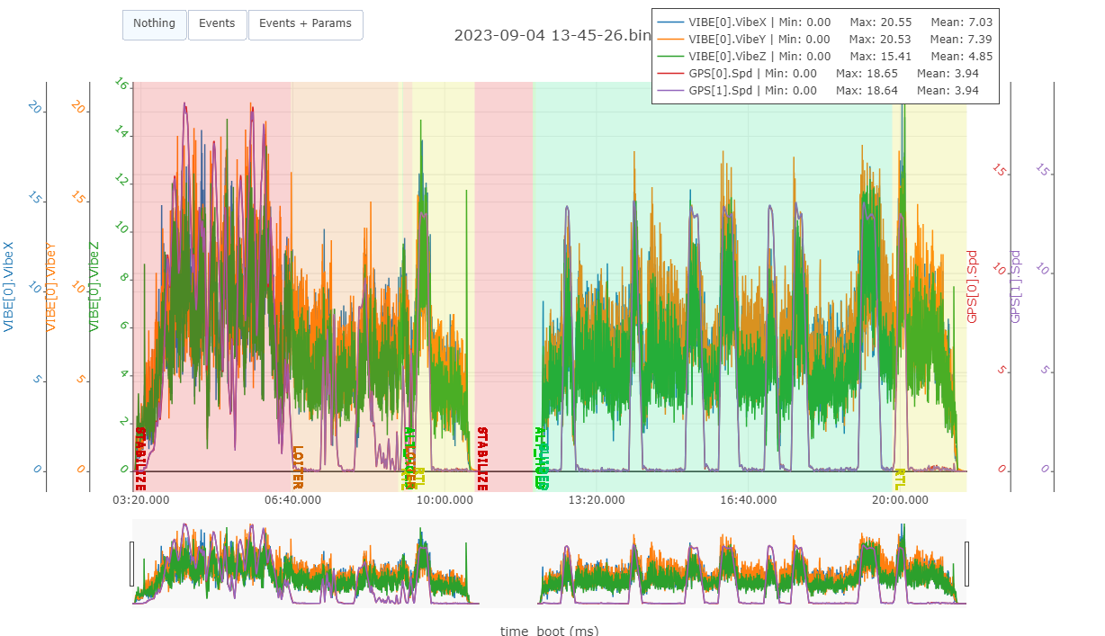
today i had test flight with all initial parameters loaded and noticed that Z axis vibration is very much improved compared to last time .
last time IMU0 and IMU1(isolated IMUs) goes more than 90m/s/s with more clippings on both IMUs . please refer in this topic for last Vibration Level.
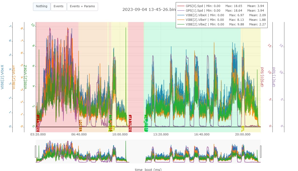
Today both Isolated IMUs goes only 40m/s/s Max even we flown upto 15m/s speed in stabilize as well as Guided mode. as shown in the image below.
That looks good, I like how you’ve done the wiring.
Z axis vibrations are a bit high, but X and Y are good.
When the cover is on, is the GPS cable not causing a problem?? I’m just wondering what would be causing the high Z vibrations.
Does the cover vibrate where it attaches? or in between the attachment points?
You definitely should set these:
BATT_ARM_VOLT
BATT_CRT_VOLT
BATT_FS_CRT_ACT,1
we have flown at speed of 18m/s max to see the peaking vibration and its not increasing more than 20m/s/s on X and Y axis. Particularly well improvement on Z axis.
i have checked the Log Attitude graph for Roll, Pitch and Yaw and looking good but RATE graph roll &pitch look like need to be improve.