That’s just a manual edit I made because it’s easy enough to translate either during JSON creation or during the element text insertion. Doesn’t much matter either way.
But yes, the array index (plus one) is the motor output number, and the explicitly defined number is the letter order as shown in MP and on the diagrams.
There is a good reason for that. Any configuration runs the same motor order with respect to the letter designations. This was done purposefully. Yes, many have complained but those that do may not get the logic behind it.
This is that json (renamed to txt for upload): motor_layout.txt (42.5 KB)
Currently it gives the “class” and “type” those match up with what the config prams. Then you get a array of motors each with number, testing order, rotation direction and roll/pitch factor.
I could easily add a string name too.
Its auto generated from the cpp code, only works for the “matrix” type layouts, but we could manually add the few others, tricopter ect.
Guess there’s a little trig involved to recompute the rotation angle about the origin - no real issue there, it just doesn’t read as cleanly as the C++ arrays.
A string field for the name would make a lot of sense. We can override anything cryptic with a custom name (probably within the wiki doc’s script).
Next step for me is to actually finish reading the wiki’s wiki and set up its build environment. I’ve never bothered since simple text edits don’t really require a full site build for testing before a PR.
I use the same roll and pitch positions to plot the motor layout in my little matlab tool for my conference talk. Using them directly works as X and Y locations works. Things like octo H and V come out correctly. The only slightly tricky bit is coaxial motors where you have to use the testing order to work out which should be on top as they both have the same XY location.
Ok, this isn’t going to be as difficult as I thought! I just installed the build environment and jammed that entire webpage into the wiki doc as raw HTML, fully expecting it to fail or render bizarrely. Nope…success!
Sure, it can use a little refinement, but I didn’t expect such immediate results.
I’ll split the script to a .js file, include @iampete’s JSON, tidy up the SVG element, and go from there!
Last step will be to automatically create the JSON during the build and also account for any frames that don’t play nice with the procedurally created output. I’ll get as far as I can and make a WIP PR for potential help with the JSON build.
It’s my understanding that ArduPilot paid for the design of these diagrams a few years ago, which explains why newer frame types are missing. At a minimum, this overcomes that issue.
I have made a few minor PRs to Mission Planner along with one pretty significant one (to me) that added some spiral path planning features. Definitely not my area of expertise, but if I get bored enough, I can have a go at improving the motor test page…maybe.
Making some progress using the JSON output from Pete, but there are a few niggling issues to solve.
Scaling the elements to fit all motors neatly is proving somewhat challenging (without a bunch of stupid magic number workarounds). I think I can get a one-size-fits-all solution by converting the JSON roll/pitch values to polar coordinates. The H and V frame types are particularly ugly with my current algorithm.
Once I can display all of the 2D frames well, it shouldn’t be hard to get the coaxial frames to play nice with pseudo-3D imagery.
I’ll make a WIP PR soon for anyone interested to see the progress.
For now, I’m quite happy that the JS and HTML are much tidier than the sloppy file I shared earlier in the thread, and the results for most frame types are pretty clean.
I’m sure I don’t get the logic, despite building with Ardupilot for 10+ years… But why are there letters AND numbers? And why don’t they agree with each other?
A should be 1
B should be 2
C should be 3
Etc
But, why are there two different designations to begin with?
With all the focus on safety and procedures, etc, it seems to me that having both letters AND numbers that seem to disagree with each other is a huge “link in the chain” that can result in accidents.
Part of this also has to do with the fact that if we were to change the numbers for some reason - how would we make sure that we don’t mess up current setups during firmware updates and whatnot? Too much of a risk with so many aircraft already flying with the current numbering.
The logic is pretty clear if you study the way AP creates and uses motor matrices, though a change to Mission Planner could potentially abstract that perceived complexity (and source of confusion) away from the user. There’s an existing, parallel effort to at least make the MP motor test page a little more intuitive.
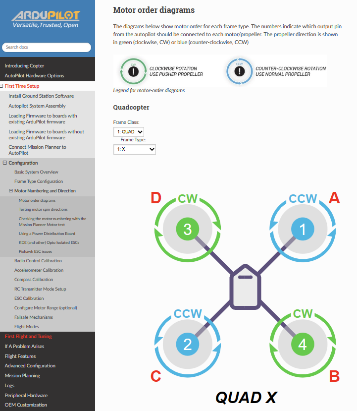
The numbers indicate the SERVOn_FUNCTION motor numbers based on physical location, so it should be easy to determine which ESC should connect to which physical output pin on the autopilot, and likewise correctly assign the SERVOn_FUNCTION parameters.
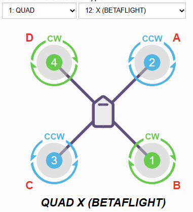
Let’s use the Betaflight ordered QUAD X frame as an example. For a user transitioning an already built copter from Betaflight to ArduPilot, no motor output rewiring or mental gymnastics are required. Also, when using a 4-in-1 ESC with silkscreened numbers that match this layout, the wiring becomes intuitive.
However, ArduPilot always treats the forward right quadcopter motor as “motor A” (or motor index 0 in the matrix). In that way, all quadcopter X frame layouts are essentially equivalent with respect to the control scheme, regardless of output order/wiring.
Maybe that’s helpful?
I would like to see a change to Mission Planner’s motor test page that incorporates these diagrams (or some variation thereof) and make each motor a clickable button for testing. After each test completes, a message/dialog could ask the user to click again on the motor that actually spun. After testing all motors, the output scheme could be corrected automatically if any errors existed.
Minor update - I haven’t forgotten about this project, but progress might be a little sporadic. Won’t have much time for it this week. Happy to hear suggestions (or accept PRs to my fork), nonetheless.
There’s some understandable resistance to the page design I’ve suggested. @hwurzburg brings up a valid point that displaying all frames at once may be preferable. Curious for further feedback before I put more effort into this.
Understood, Henry. I’ll have a look into how the parameter lists are generated during the build (because it looks like they also use JSON as the data source) and seek to do similar with the JSON defs for the diagrams. Not a major obstacle there.
Then we can address proper display of the diagrams overall.
I can see the preference of why someone would want to see all frame layouts at once. Since that might be the path of least resistance at this point, I think we should focus on that page layout.