So they shouldn’t post example diagrams. Instead put a pin out in a clear table like CubePilot does or make a diagram that depicts only their hardware pinout without showing hardware that may have its own pinout.
I have personally miswired multiple connections due to poor documentation, Matek’s diagram clearly depicts generic 4in1 ESC implying that all such ESCs use the same pinout.
matek dont make any ESCs. It was clearly an example.
There is a certain amount of assumed knowledge by the ppl drafting the fc manuals etc, but not much.
Getting a new build working properly will involve a fair bit of reading, looking at spec sheets, diagrams etc and teething problems when you turn it on.
I have always found the matek info for their fc to be sufficient to get the job done, but sometimes you just have to join the dots or put two and two together. Ive done a fair few builds and yet to find any actual mistakes in the matek wiring diagrams, pinouts, port assignments etc but these are diy components, you will have to work out what pin connects to what other pin and so on, ive gotten pretty good at pulling the pins from the standard connectors and swapping them around so it suits the connected device on the other end. Its mostly not just plug and play, unless you buy all holybro components that are made to be connected together or something like that.
Lupus, I see that you tend to agree with me.FYI, I have copied part of a letter I sent to Matek about this issue stating that they should remove the ESC pinout diagram. I even sent them a suggested diagram that would have been much better.
Has anyone seen a schematic of the Matek H743 mini???
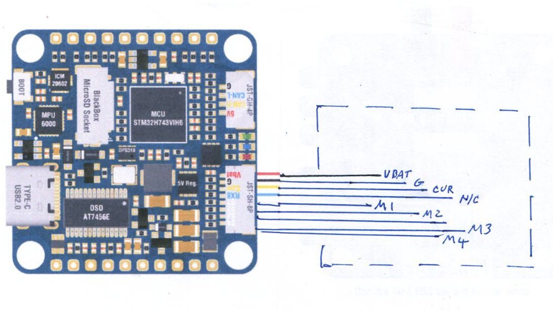
On the wiring diagram for the Matek H743 slim, I think you should change the FC to ESC diagram to something like what I have attached.
Let me explain why.
I am new to the drone business. Your FC, the Matek H743 slim was recommended to me by a person on the Ardupilot chat site.
I asked a person at GetFPV what I should use for an ESC and the JHEMCU BS 40A BLHeli_S was recommended. I bought both parts and started to build my drone. Hindsight tells me that I should have bought a “stack” and I would not have to wire the two together myself.
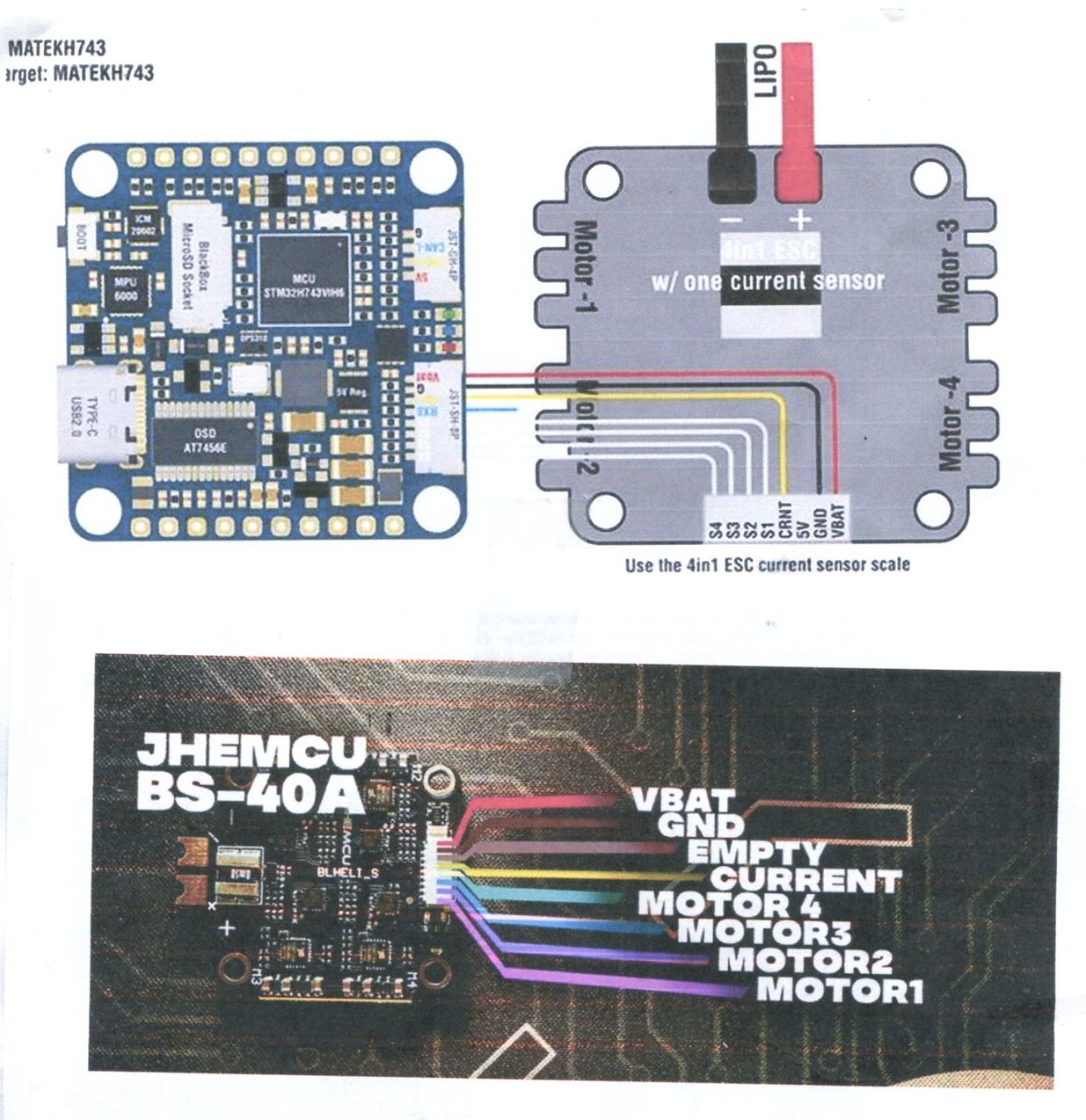
Being a newbe, I looked at your wiring diagram that showed th FC to ESC wiring. The ESC shape on your WD is exactly like mine, even the power pins and motor pads, so I thought, hey, this is easy, just connect Vbat on the ESC to Vbat on the FC and all will be good. There are no markings on my ESC so I relied on your diagram. Unfortunately, Vbat on my ESC is next to M2, not Motor-4. I took your diagram as being correct for my ESC, obviously it was not. Even the motor numbers are reversed.
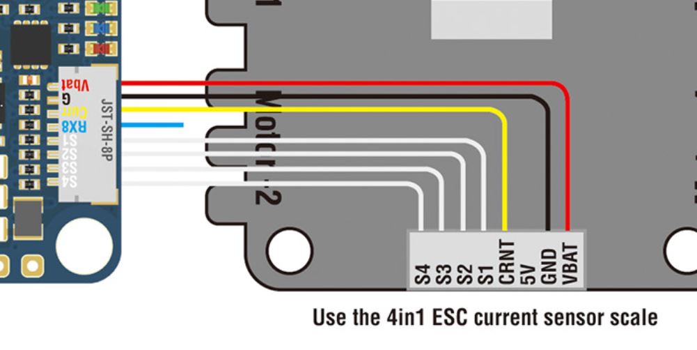
Notice in the diagram I attached, I removed the shape of the ESC (in fact you do not even need to show the ESC at all). Had I seen this, I would have been forced to find out, from some source, where Vbat, Gnd, Cur, M1,M2,M3,and M4 was located. Since the ESC I bought was made in China, getting info about this ESC is difficult. Fortunately, GetFPV had a diagram on their site. Had I seen this before I started wiring, I would not have made the wiring errors I did.
Many people have told me something like, " Hey, you should know all ESC are different and you can’t rely on this diagram." I am a newbe, I do not know all of the answers yet, maybe at some point I will. I think that if I cannot rely on the ESC layout then it should not be there, as it is very mis leading.
1 Like
Yea, the same one on their website I have used for this Flight Controller.
In fact here is the illustration I produced (not rocket science) to wire it to the ESC I used. It could be any ESC…
Please post the URL of the schematic. I cannot find it on their website.
Page down, the Wiring Tab is shown.
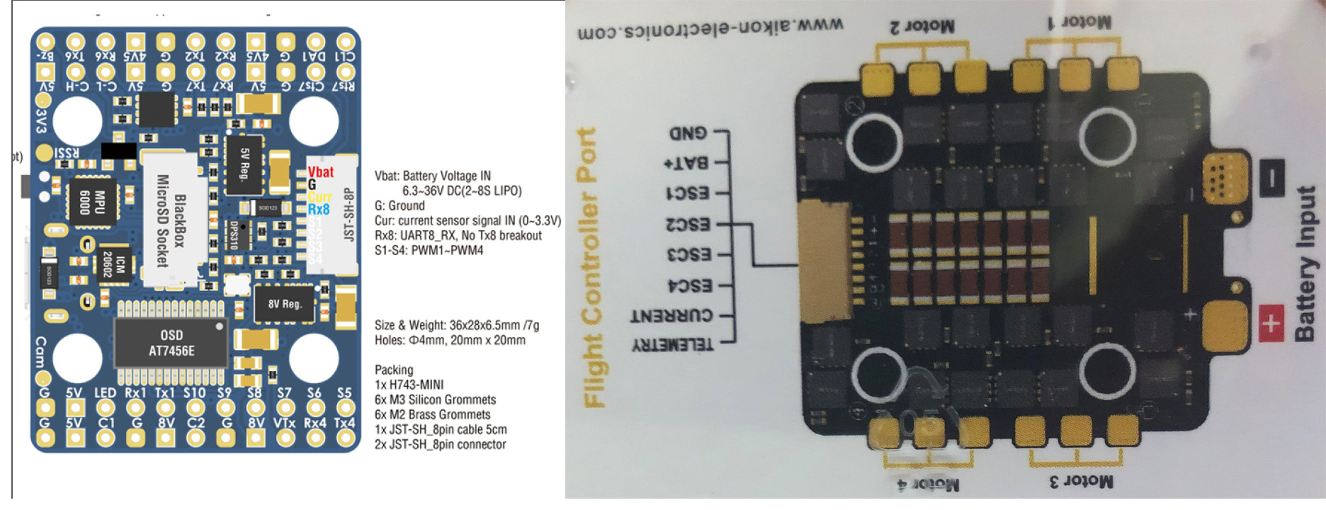
Matek H743-Mini
Sorry Dave, that is not a schematic. It is wiring diagram showing how to connect external components. I hope this is better than the one for the Matek h743 slim, the FC I have.
It’s no different and there is no expectation that there will be. It’s the most common practice in the hobby. You would expect that Matek would produce a wiring diagram for every 4-in ESC available? They don’t even make an ESC. Holybro makes FC’s and ESC’s, perhaps you should try their products?
Is this what you want?
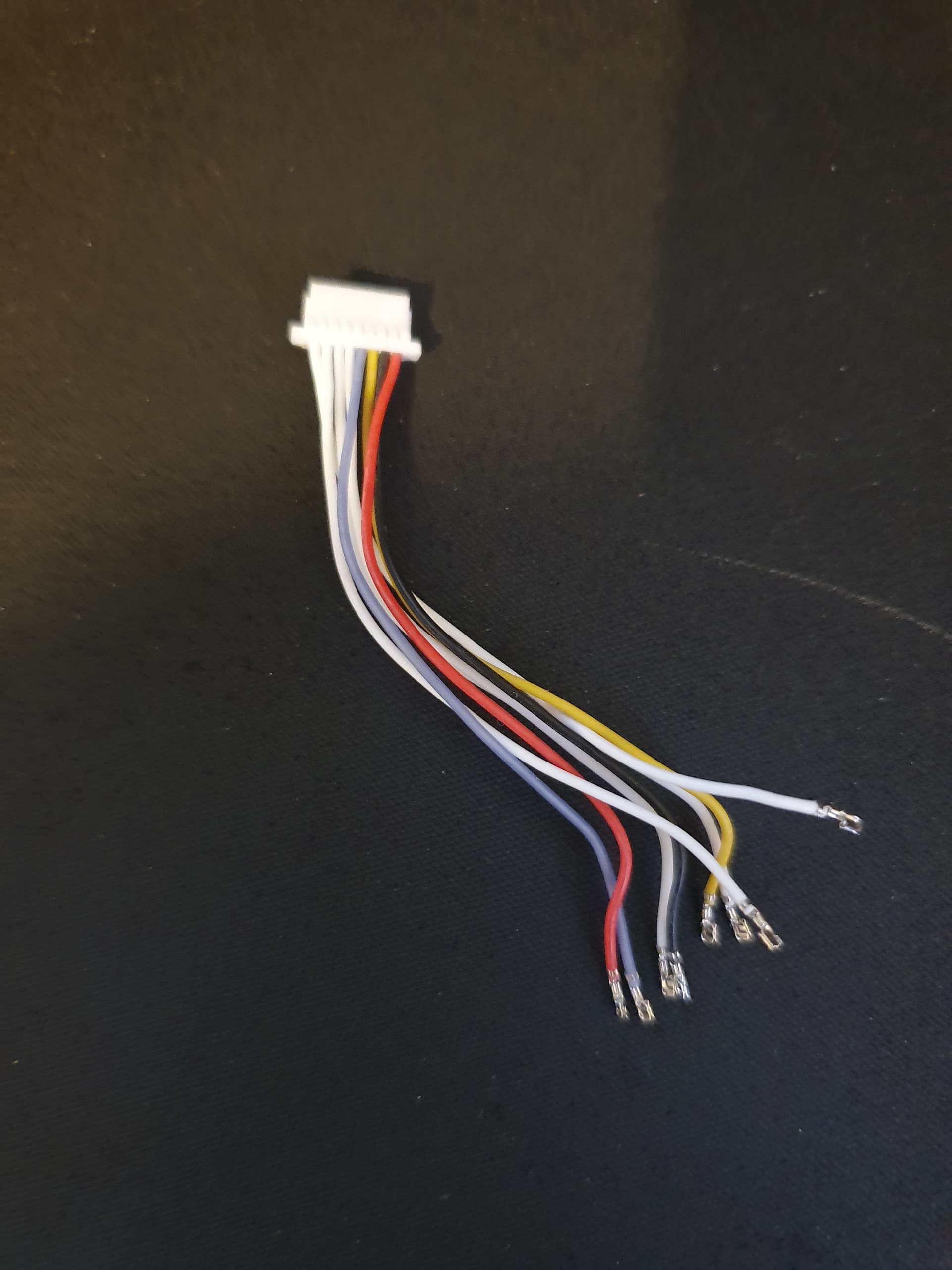
What cable did you actually use specifically, because this is the cable that comes with the h743 slim. You have to add the wires to the second connector yourself. its not like matek wired it up wrong, their end that is pre pinned is correct. Did you not think it was strange that they would leave one end unconnected if there was a standard?
Now you are being ridiculous. Everyone knows what a schematic is. Other than some of the Open Source Flight Controllers these are not available. Certainly not from Matek. And why would you need it anyway? All you need is a function to function illustration.
Geo, Yes I saw that cable and yes I know it had to be connected. But I will sayh it again, and again, and again, if you look at the WD from Matek the Vbat is shown next to the “Motor-4” side and this is totally incorrect. Had I pinned a cable like Matek showed on their wiring diagram with Vbat on the Motor-4 side the wires would be reversed and this is what I did.
Dave, No, I am not being ridiculous. Lets be specific. A wiring diagram showing external components, i.e. how they should be connected is NOT a schematic.
every matek diagram you have shown has shown the same order, what one one is inconsistent with the rest?
Geo, LOOK! The Matek WD shows Vbat next to “Motor-4” Look at the Matek diagram and convince yourself of what I just said.
Now look at the othe image. I ask, where is Vbat??? It is next to M2. It is not shown next to M4. Just look at it.
In addition, not that it matters a lot but look at the order,
Matek JHEMCU
Vbat Vbat * Matek Vbat is next to Motor 4 JHEMCU Vbat is next to M2
Gnd Gnd
5V Empty
Crnt Crnt
Mot 1 Mot 4
Mot2 Mot 3
Mot3 Mot2
Mot 4 Mot1
I don’t think the motor order is bad enough to cause issues but there is a difference.
Just look carefully!
thats not from matek. I said what matek diagrams are inconsistent.
What are you talking about “Motor-4”?
And the Motor order makes no difference. This is always confirmed and corrected if required in Arducopter configuration.
ardupilot does not use the same 1234 order as betaflight so even if you had them the same it still wouldnt work. It has to be changed to ardupilot order by either reordering the wires or in software.