So what? This is no more difficult than connect the dots. The orientation of the ESC, either ESC, makes no difference at all. You are really saying you can’t connect function to function?
Matek cannot control how other companies make their escs, that is specifically why they supply the cable without a plug on the end as not all escs will have the same functionality or pin order. if they supplied the cable with it pre wired on both ends you would have a point but YOU wired it wrong.
Dave, can I use Ardupilot config to switch Vbat with Motor 4? I don’t think so.
Anyway, after realizing the Matek WD is very misleading, I found the JHEMCU image, realized the wires were reversed and corrected the issue.
Fortunately it seems the FC was not damaged by connecting 12V to the Motor 4 pin of the FC.
1 Like
Geo, I wired it like their diagram showed
I provided that image to you before you connected it.
Absolutely not. You did not supply the JHEMCU image.
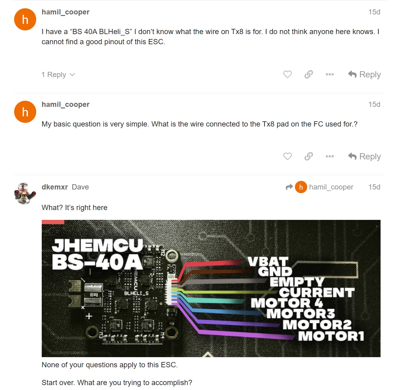
The issue is this. My JHEMCU ESC does not have a place where Vbat is marked . So without the BHEMCU image how would I know where Vbat was located. No problem, I assumed the Matek WD ws correct, it was not, so I wired the Vbat to the wrong pin. Then I found out that the FC ESC did not work and discovered that the 12V was on the wrong pin.
Another issue I have not mentioned is that while pushing the connector into the Matek jack, it broke off. I now have to solder to the pads directly on the FC. This is not a problem as they are labeles very well.
You had the image, I provided it.
ESC pinout
The4 image is in another thread I think where we were discussing what the extra pins on the FC were used for. I though they were for telemetry but you pointed out that the only feedback from the ESC was the current wire. At that time, we had not discussed the mixed up wiring.
This image is not on this thread.
Sure but you claimed I did not provide the image (absolutely not) and I did and then you said
So without the BHEMCU image how would I know where Vbat was located.
You did have it.
The image is not on this thread is it? I looked for it.
However, I assume you did provide it in another thread but we were not discussing the re-ording or the out of order, or reverse wires were we? Whether you provided this image ina previous thread under a different topic does not matter. The Matek WD is misleading.
Lets just drop this topic, OK. I see we are not going to agree.
We are definitely not going to agree because the Matek illustrations simply indicate what the connector pin functions are and they are correct. The ESC connector pin functions are correct also. What wasn’t was how you connected them.
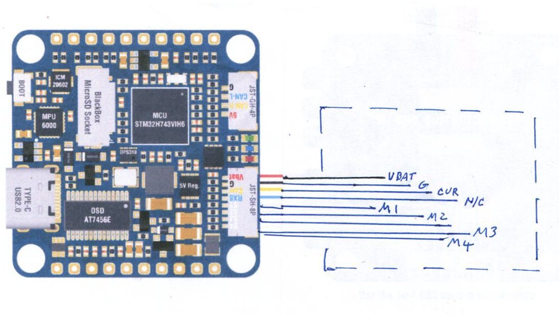
Anyway, like I said, it looks like no damage was done. I have not turned the motors as yet but the PWM signals look good and they change with the radio lever movements. I thin Matek should put a diagram on their site like the following where it does not show any details of any ESC at all. This way there would have been zero confusion.
Also, for some reason, the connection between the Gnd of the ESC and the Gnd of the FC did not connect. This caused wierd voltages to appear. I connected a wire directly from the Battery Gnd to the Gnd on the FC and things work out much better.
I just have to ask. If my ESC had a telemetry output where would I connect it on the FC? It is not shown on the diagram?
As discussed in the other thread ESC telemetry data is connected to a UART. The RX8 pin on the Matek connector is made available for that purpose. UART8 on this board is Serial5 in Ardupilot so the protocol for ESC telemetry would be configured on that port.
I was just pulling your chain a bit Dave. I just had to point out that the Matek WD did not show this connection. In this case I would have had to look it up.
It wouldn’t because there are other ESC’s like yours that don’t have telemetry. Of course they have no control over that. And it could be used for any Serial input really, it doesn’t have to be for ESC telemetry. It’s on the connector for convenience. Many use Bdshot and don’t bother to connect the ESC telemetry because you get the most important function, ESC RPM, thru the Motor outputs (di-directional input/output actually).
Many times you can get more targeted Ardupilot data from the Ardupilot Wiki for the boards. This entry for example:
Matek H743
Because Matek and other boards can be used with betaflight or iNav you need to review the details targeted for Ardupilot. Matek actually does a better job than most by having a dedicated Ardupilot supported hardware page and pin mapping.
Dave, One final final comment. In your above post you mention telemetry. Lets assume I bought an ESC with telemetry. In the Matek WD no ESC telemetry is shown so I would be forced to ignore this diagram and look elsewhere for good wiring information. So, in the future when probably everybody will b e using ESCs withe telemetry, this WD is of no use. If it is of no use, then why have it on the diagram at all. Useless information can be misconstrued as being useful in some cases, like mine.
The solution is to merely show the pinouts of the Matek FC going nowhere, like the hand sketch drawing I presented earlier. With only the pinouts listed, with no ESC “example” thje newbe would be forced to do some research to find where the appropriate pins of the ESC are located.
Looking carefully, on the Matek WD, the RX5 pin is shown going nowhere. Wouldn’t it be better if that wire stub was labeled “telemetry”?
People answering in this forum should not assume every question is from a knowledgeable person. Answers like RTFM and go read the documentation, that you did to me earlier is of no use and a total waste of bandwidth.
Anyway, most of my issues seem to be solved now. I received some new USB 3 C cables from Amazon that seem to work. Even the 10 foot cable.Today is a day to calibrate accelerometers and compass, I think.
Have a good day.