I just wired my ESC to my FC using the wiring diagram that Matek provided. Unfortunately, the ESC figure was wrong therefor I wired the devices together wrong.
A lesson learned. Do not trust the wiring diagrams. Double check the connections. It was probably a $100 mistake.
I’m very concerned about this happening, so I always check the motors in sequence before the first flight to see if they are in the position they should be and the direction of rotation.
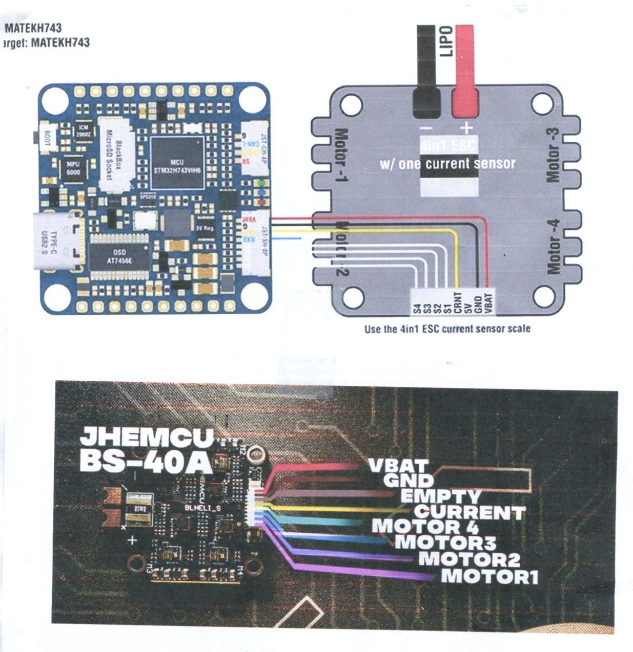
I will show you two images. They do not agree. Aparently, there is a steandard that the ESC people should follow but the one I bought, recommended by someone here, does not support the standard. As a result, my wires are crossed. In the two figures, notice that on one, the Vbat is next to M@, on the Matek diagram, Vbat is next to Motor-4. Also look at the motor sequence, one is 1,2,3,4 and the other 4,3,2,1.
It’s obvious you have to re-pin the connector. I and everyone else has done that on every build. There is no standard, every ESC manufacturer could be, and probably is, different. I know the T-motor, Aikon and Airbot are just to name 3 I have used.
“Bad wiring diagram” is not an appropriate title for this.
Maybe a misleading diagram would be better. You must agree that the Matek WD does not look like what is on the ESC image, right?
When I started my project I found that good wiring diagrams are hard to find. In fact, this one is from the GetFPV site. I cannot get a WD from the manufacturer so far.
When one starts a project they assume, and of this of course is bad, that the diagrams are correct. This outline looks like my ESC, but the wiring is wrong.
Anyway, Matek should probably just label the pins on their FC and not show wires going to an ESC because there are different ESCs to consider.
I don’t think so. Nothing at all wrong with it. If there was you would not be the 1st to point it as these are very popular boards all over the forum. You connected it wrong and apparently smoked the board. OK bummer, but that’s it. I suppose you connected Vbat to something you were not supposed to connect? Didn’t we discuss this already in another thread?
Yea but so what? It’s an example of one of many showing function to function connections. These types of illustration are all over the hobby.
It is still misleading. Had Matek just labeled their pins with no additional wiring, I would have searched for the correct WD for my ESC and no error would have occured. However, they put an incorrect diagram on their website and I assumed they were correct. No so.
If the information is not correct, then don’t publish it!
If you showed that to me I would assume that your diagram is wrong and go to the source for the correct diagram.
I fail to see the point of this post. If it was titled “I smoked my Matek board by miss-wiring it” and then explained how you did so that at least would help others avoid it. Everyone else has seen that same diagram and built correctly.
For anyone else reading this let’s go back to your previous post and understand how you were able to get this wrong: FC/ESC wiring
There are no connection standards, Unless you bought it as a set you need to check what the pins are on each device and order the wires to match. The pinout in the diagram for each component is correct, you made the error by not checking the wiring was going to the right place.
The only controllers with a connection standard are the pixhawk variants, but even then there is a difference between pixhawk 1 and all the newer, pixhawk versions.
That’s a proposed betaflight standard. Matek may choose to support it or not. There are other standards, Droncode supports one. The problem is not a standard and some FC’s and ESC’s Don’t even have the same number of circuits on these interconnects.
But, the title of the post is now accurate in any case.
Perhaps so. Building RC craft isn’t for everyone and mistakes and failure happen. I lost a DJI Mavic Air in a river. It wasn’t the fault of object detection it was my fault for overestimating it’s capability. Expensive lesson but I don’t think i’ll lose the Mini 3 pro in a river…
I don’t think wiring up things is a rocket science job. It is easy if you start with correct information. Now my challenge is to determine what has been destroyed. I think I should be able to run my ESC from my PWM radio receiver outputs. In a similar manner one would think that I can look at the PWM outputs with a scope and see if they work. The puzzle for me now is why there is no continuity between the Battery ground and the Ground wire going from the ESC to the FC. Seems like there should be.??
Did you connect Vbat to the wrong pin? If so what pin? What’s the symptom of it not working? If you connected it to a motor output the FC is likely shot.
Actually a new post would be best for troubleshooting assistance.
Yes, by wiring per the “good” WD. I connected Vbat 12v to Motor out 4 or was it 1. Whatever it was with the wires. The FC works when powered from the Computer USB. All functions work. I am thinking about driving the ESC from the PWM of my radio receiver to see if it is still working. Anyway, I am having fun.