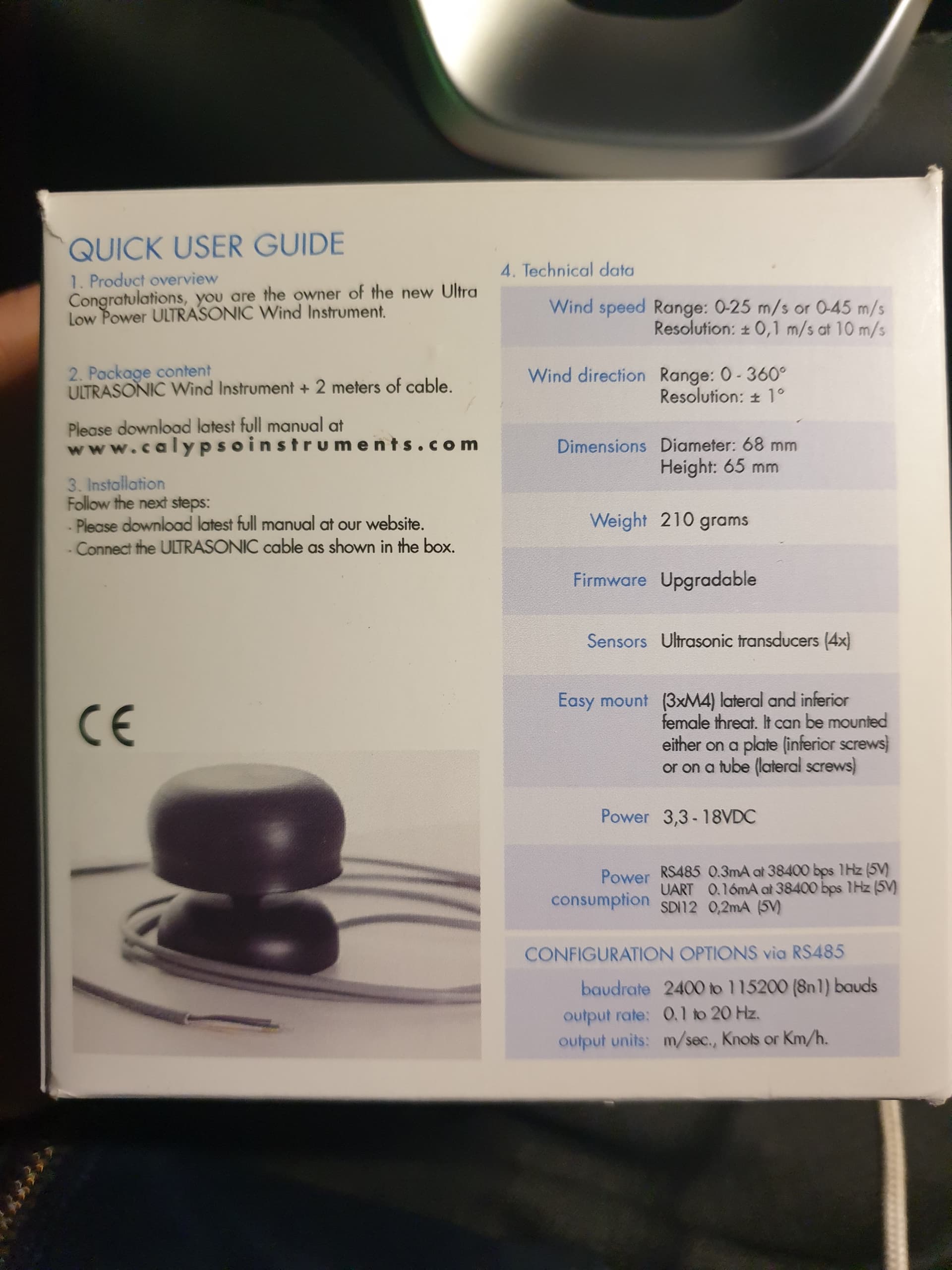
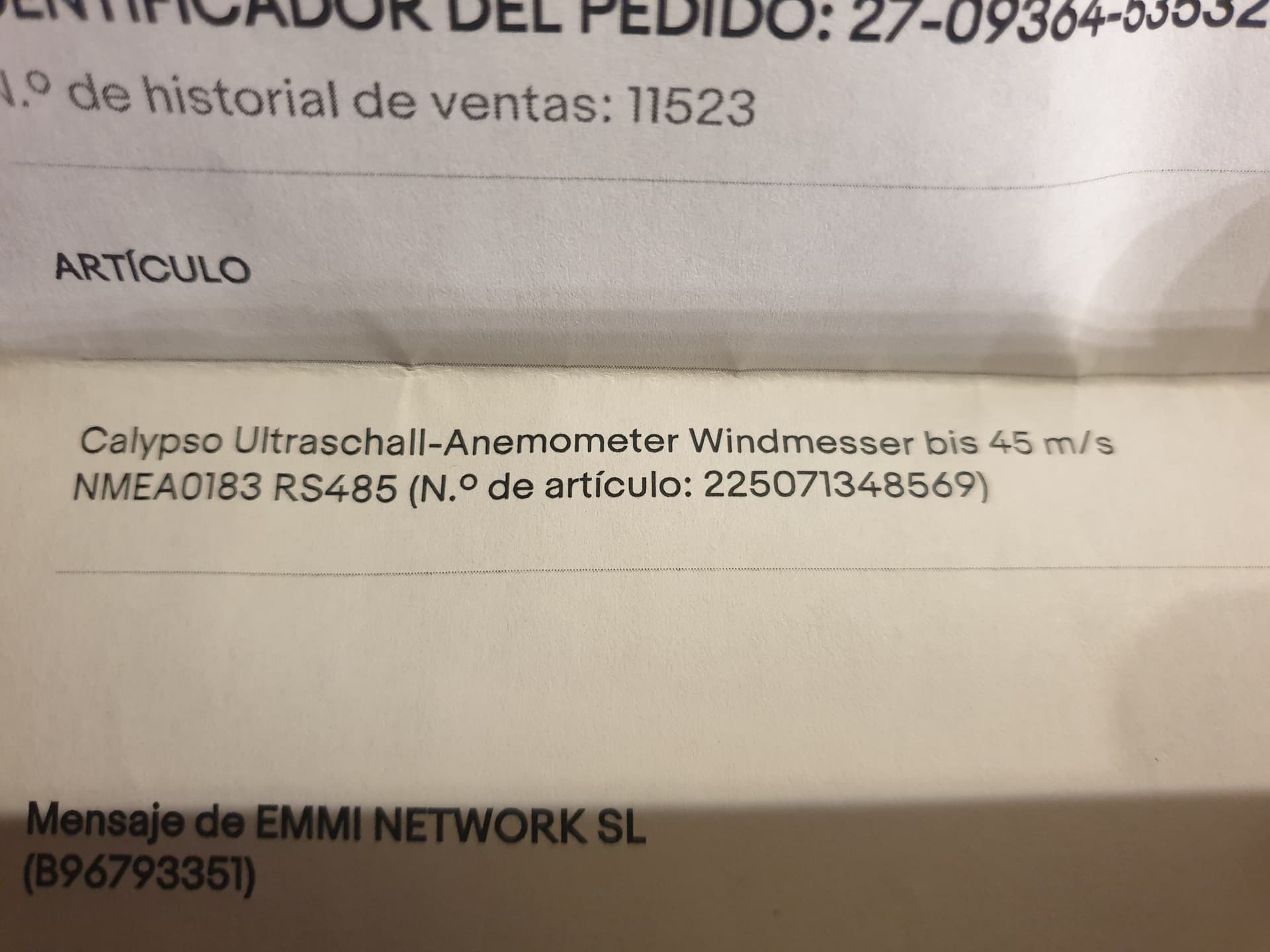
Hi, I just purchased the Calypso ultra low power ultrasonic wind vane (see pictures) will this work for my sailboat as wind vane?
If you have the NMEA 0183 version then it should just work per the wiki. If you have the uart version we would have to add a new driver, but it should not be too tricky.
1 Like
Does the UART version use a different data protocol than the NMEA0183 RS485 version?
After looking over their manual, it seems like the only difference is the RS485 physical link vs a direct connect using 5V TTL. The RS485 version has the benefit of longer wire runs without having to worry about noise. The RS485 version also draws a bit more power to power the RS485 electronics.
I’m not at all sure, but I think the UART version should work fine without any driver change. (Of course this doesn’t matter for this specific case.)
Of course if someone purchased the Modbus version, the driver would need to be changed (assuming there isn’t already Modbus support).
I also bought the Sparkfun Max3232 in this picture, but what is the other board in the picture? Is it just a power module?
I use a kit like this to control the sailboat, so how should I connect the Calypso wind meter? Do I need anything else?
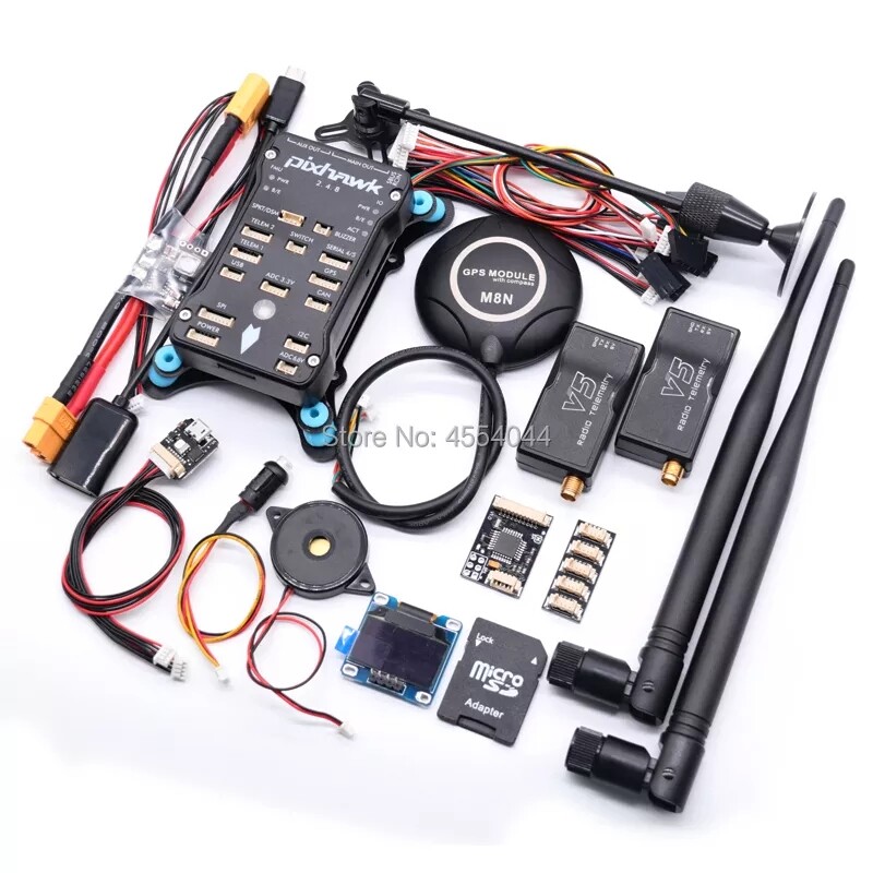
Its the flight controller, this one to be exact:
https://ardupilot.org/rover/docs/common-holybro-kakutef7aio.html
Okay thanks, but how would the wind meter be connected to my pixhawk?
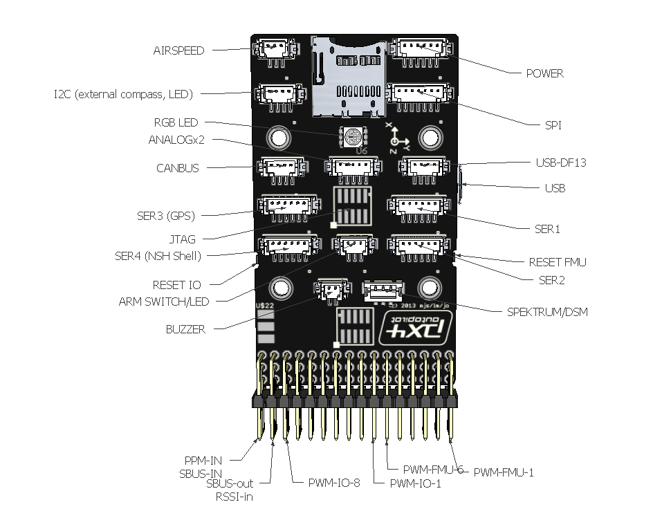
https://ardupilot.org/copter/docs/common-pixhawk-overview.html
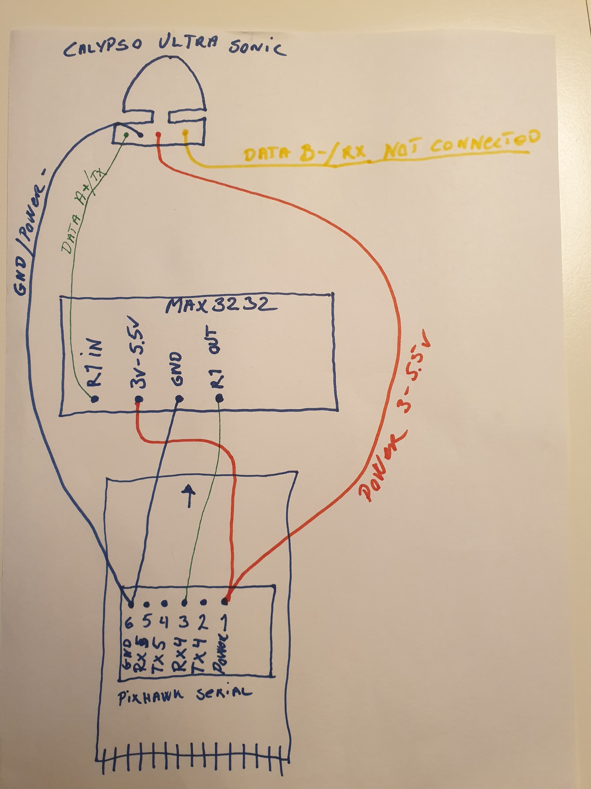
In this link there is a description of the ports/pins of the Pixhawk 2.4.8 that I use. But could someone more hardware experienced than me ( @iampete ![]() ) explain how I should connect the 4 wind meter wires with the Max3232 and Pixhawk pins?
) explain how I should connect the 4 wind meter wires with the Max3232 and Pixhawk pins?
Thank you in advance!
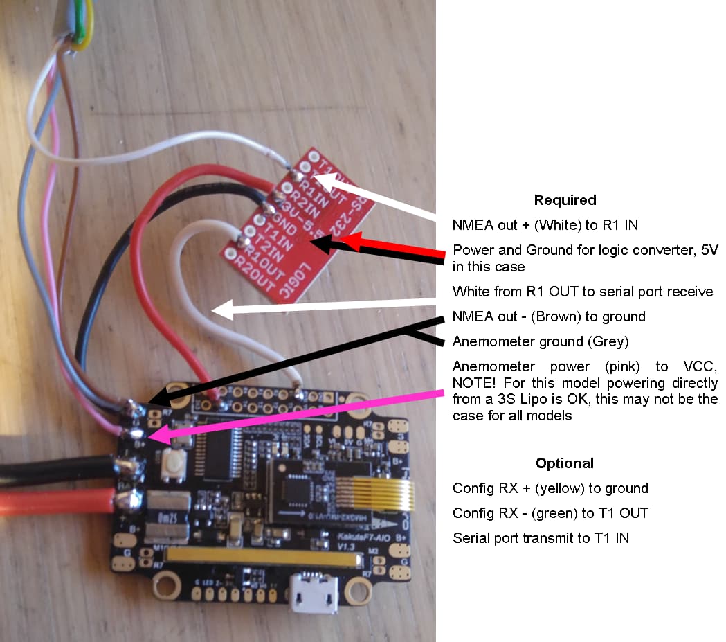
To my knowledge, this bit of the above link is the port that I need to connect the wind vane and Max3232(if at all needed for my Pixhawk)
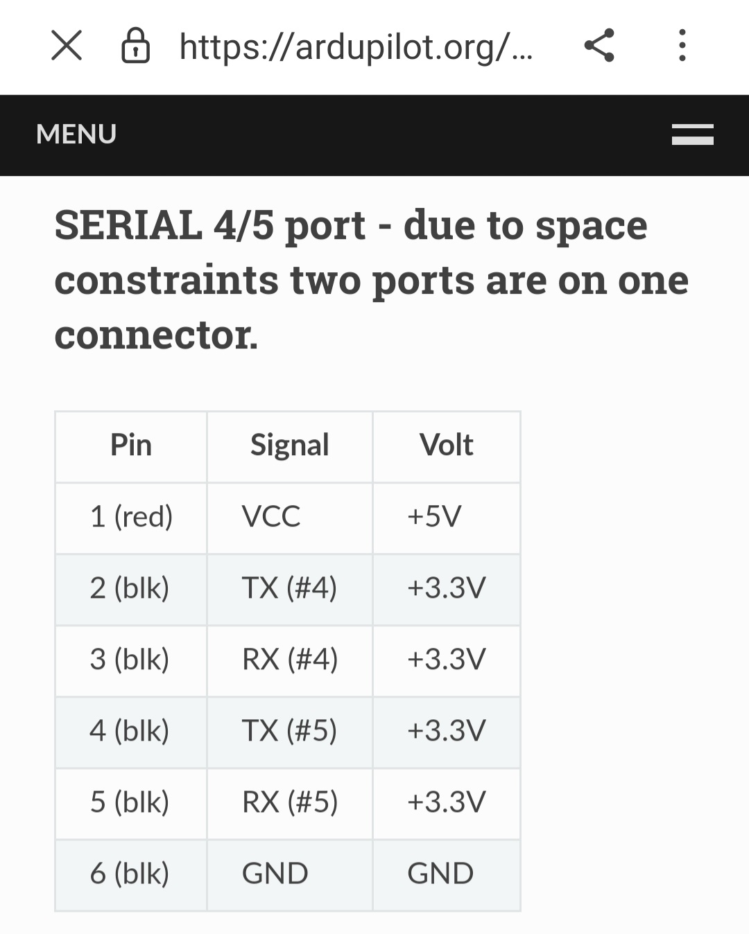
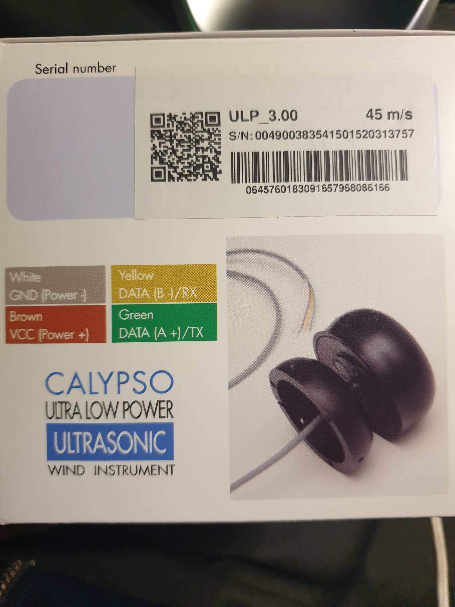
Connect the same as the wiki example diagram. Except you use the green “A+” wire instead of the white “out +”.
1 Like
Does this look right to you @iampete ?
I’m trying to figure out why a MAX3232 chip is used. The MAX3232 chip used to convert between RS232 and 3.3V logic. The Calypso is a RS485 device; I’d think you’d need a RS485 transceiver to interface it with something using 3.3V logic.
If you’re not familiar with the difference between RS232 and RS485, you should take a look at the appropriate Wikipedia articles.
Both the D+ and D- lines are used together to transmit data.
It looks like you have the wrong type of transceiver to me.
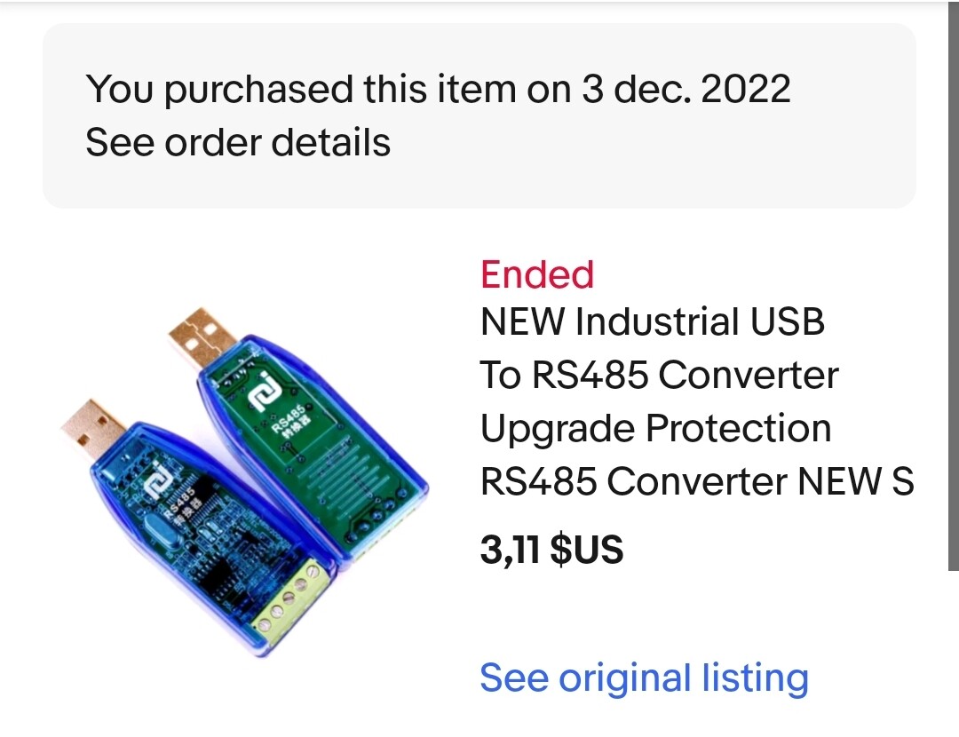
While purchasing a RS485 to 3.3V transceiver, you might want to pick up a RS485 to USB device so you can test your Calypso with a terminal program on a PC.
Hi Duane,
I am no hardware expert so I take any advice ![]() and to be on the safe side I purchased both items you write about, can you tell me how you would wire the three components together?
and to be on the safe side I purchased both items you write about, can you tell me how you would wire the three components together?
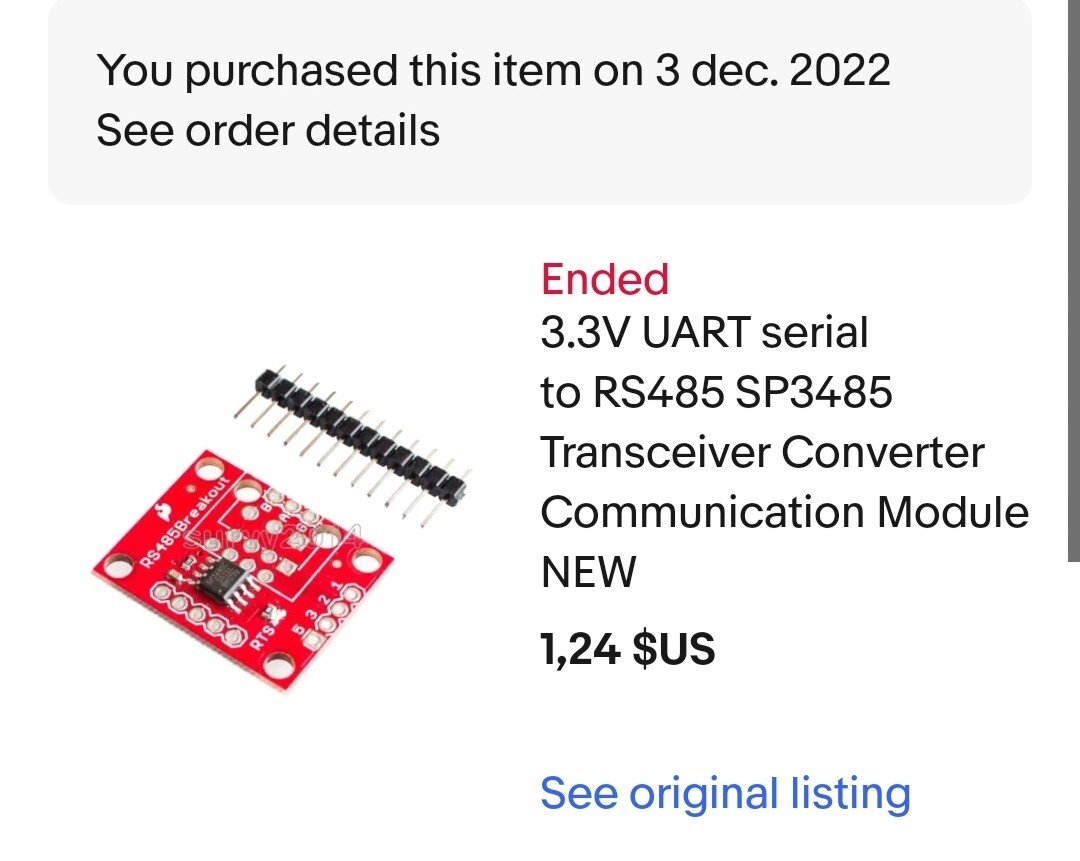
Here is a diagram showing the pin names of the transceiver chip.

The D+ and D- lines from the sensor connect to the “A” and “B” connections on the transceiver chip. Which line is considered “A” and which is “B” depends on the manufacture of the transceiver chip. I’ve found these labels to be inconsistent and you pretty much have to swap the two wires and just see which way they work.
The data lines of a RS485 are balanced pairs. When the voltage goes up on one line, the voltage goes down on the other. Using balanced pairs like this makes the signal much more immune to problems of noise. The transceiver takes the two signal lines and converts to signal which the flight controller can use. The datasheet calls the data out line Receiver Output (RO) (pin #1 on the chip).
The transceiver can both convert the balanced signal to a 3.3V signal and convert a 3.3V to the balanced pair. You likely will only need to receive RS485 signals so the flow control pin (DE) can be hardwired low.
The Receiver Enable (RE) can be connected to ground so the chip is enable whenever powered.
I’m not completely clear on how the DE and RE lines are used. The Sparkfun schematic shows these two lines joined together.
Looking at the schematic on one the boards I designed which use this transceiver, I see I connected RE to ground and use the DE pin to control if the chip is in receive or transmit mode. If both these lines are tied low, the chip should be in receive mode all the time.
I couldn’t find a photo of the bottom of the Sparkfun board. If you post a photo, I should be able to help you figure out how to hook it up.
Based on the schematic, I think you’ll want to connect “RTS” to ground and “TX-O” to the receive position in the flight controller’s UART.
As I mentioned above, the D+/- should be connected to the positions labeled “A” and “B.” If I had to guess, I’d think “D-” would be the inverting input or “B” on the chip. Again, be prepared to swap the D+/- lines.
I don’t know enough about ArduPilot to help with the software side.
Have you used TeraTerm or similar terminal program? The RS485 to USB device you ordered should allow you to see the output from the sensor using your PC.
Thank you very much Duane! I will try and make a new hand drawing to show how I understood your description, will post here soon ![]()
1 Like
Okay I think I am lost ![]() this is what I could understand from your text - but 99% sure this is either completely wrong or just partially, can you help me connect?
this is what I could understand from your text - but 99% sure this is either completely wrong or just partially, can you help me connect?
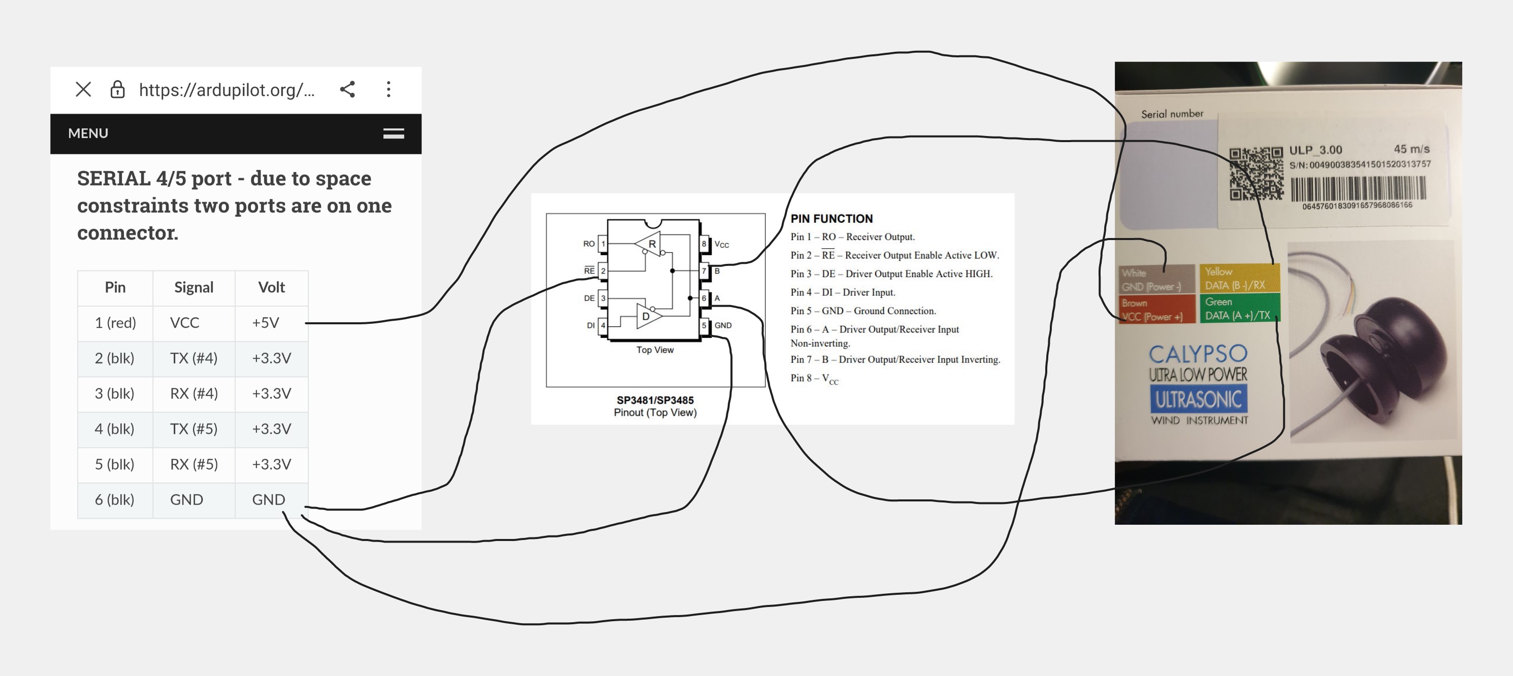
That looks pretty close to correct. I think I’d connect DE to ground. The chip should be powered with 3.3V. The RO line should connect to the RX of whichever UART you chose. Here’s your diagram with a few additions.

As a reminder, don’t solder the A and B connections. You might need to swap these.
When you receive the part, post a photo of the bottom of the PCB and we can confirm which pins to connect where.
Awesome thank you!
I will receive the parts January 2. but lets see. I will post photos when I get it.
1 Like