Hallo Denis,
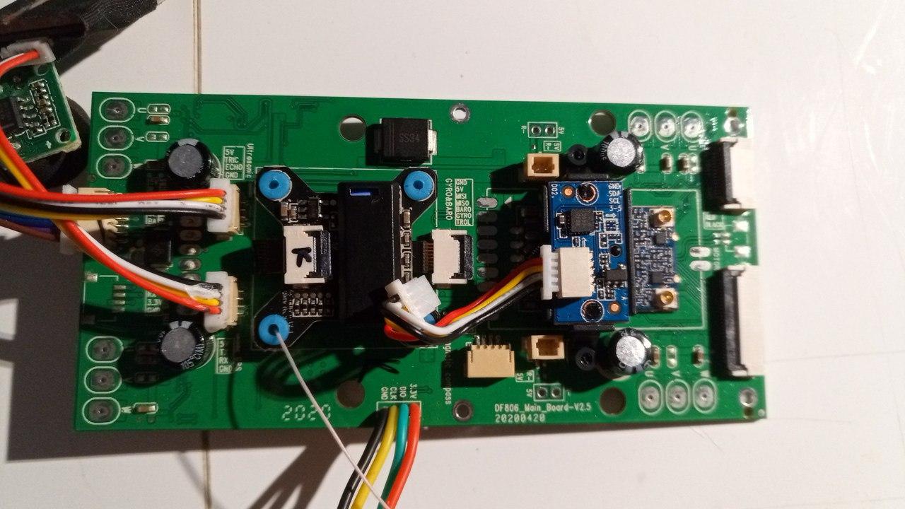
My experience with green DF806B motherboard is different, and DATA lines shall be inverted when compared to the referenced picture.
Starting from top line, for me is:
+5V
DATA-
DATA+
GROUND
Daniele
Hallo Denis,
My experience with green DF806B motherboard is different, and DATA lines shall be inverted when compared to the referenced picture.
Starting from top line, for me is:
+5V
DATA-
DATA+
GROUND
Daniele
Thanks Daniele, I’m more worried about the +5V and GND wires as they could fry the quad or the USB port. The DATA lines I think can be swapped without worries until you have a working combination, it is after all a serial communications bus so the two signal wires ought to be crossed on the other end (ie. RX on the left goes to the TX on the right).
Correct, all that really matters from a power safety standpoint is +5 and ground (earth). It’s common for the definitions of DATA+ and DATA- to be – shall we say – “flexible” – and you just swap them until it works.
great, thanks guys. my MOLEX connectors and USB sockets are still on their way from China for more than a month but should arrive soon, hopefully, then I’ll test on my JJRC X12 the Mission Planner connectivity.
That climb to 30 meters before RTH is bugging me, I’ll be changing that to 0 so the quad will just set heading for home location and get going.
Also I’m thinking about increasing the maximum tilt angle. Currently it is set to 20 deg and I think that if I increase it to 30 then the max speed will, theoretically, also increase.
I know that above 45 deg it’s not a good idea as quads do have an aerodynamic limitation in that regards, but going from 20 deg to 30 deg should not be much of an issue, just an increase in speed, hopefully. Also the gimbal tilt angle should not suffer much…I think
Setting that RTL height to zero was one of the first things I did for the owner. I also set simple mode on loiter – left it off for position hold. Various other changes. I now have the correct connector plugs (with the conductor wires preinstalled). I haven’t actually used one yet since my current wiring is still working and I’d have to clean up the glue mess in there to be able to use the prewired plug. I’ll do this if my original wiring fails.
A couple of points on using Mission Planner or QGC. Note that the drone has no SD card, and cannot save a mission across power cycles. It also won’t save logs. I’ve solved this by using a Raspberry Pi Zero W as a companion controller, which is powered from the drone itself. The Pi runs MAVProxy and dronekit-python. This enables the control link via the Pi’s integral Wi-Fi or attaching a conventional telemetry radio to the Pi serial port. MAVProxy also captures the real time telemetry into files that can be played back in QGC, so the logs are no longer an issue. The Pi is also configured to (when desired) automatically load a mission (saved on the Pi) when the drone and Pi power up.
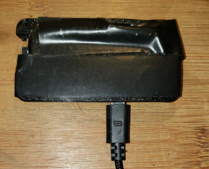
I’ll add that the Pi straps to the bottom of the drone. It’s simply the board protected by a thin stiff layer of plastic and tape, with the two microusb plugs (data connection and power connection from drone) plugged in. Note that you have to apply power to that usb port in the drone to get the data working, so in my case I’m using power pulled from a point in the drone to power the Pi and the Pi then powers the usb port through the data connector.
I think the logs problem was solved by the controlling app. At least in the latest version of the C-FLY app in the Listener folder you will get a .txt file for each flight you take. It’s not a binary flight log like the one in ArduCopter but it has sufficiently detailed information to get an idea where the quad has been, what the various inputs were, HDOP, nr. of sats, battery voltage, sonar and optical flow state. Pretty much all I need to plot a flight in Google Earth.
Better than nothing but having the full telemetry is a big plus, since you can track and graph everything for tuning in GQC. The telemetry logs play back perfectly in QGC. The other factor of course is that for this drone the C-Fly app basically is a crashing nightmare (though over time I’ve found how to sequence things to avoid it crashing on connection setups). For most missions, there’s no reason to use the app at all.
Absolutely, especially if you’re doing that sort of experiments that require full logs access. In my case the logs I get from the C-FLY app are sufficient - just want to plot where the quad has been to “show off” to my friends. Actually it’s more of a check I do on my flying afterwards.
I tried adding a RPiZeroW to my other bigger quad, a Cheerson CX20 which has 12V power plugs for a gimbal and some extra, the problem was I could not get the Pi “compact” enough to hang under the quad, it already had a gimbal that occupied the whole space. My plan was to use the Pi along with a MLX90640 thermal camera (it has only 32x24 resolution but when interpolated it’s usable) and then transmit a data flow to my ground station, basically use VNC to access the Pi over its wifi and see what the thermal camera sees. A really “poor man’s thermal camera” but it does work. The trick was that since I could not fit a Pi under the quad I had to resort to a Teensy 3.2 with the MLX hooked to it along with an nRF24L01 transceiver. The receiving end was also an nRF24L01 which at first I tried hooking to a Pi Zero but for some reason the Python libraries I had did not want to communicate with the NRF module so I went the way I already knew: hooked a Arduino Nano onto the NRF module (good old trusted setup) then over serial I hooked the Nano to the Pi.
Since I already had the Python script for this particular setup it went like a breeze to get the data feed from the quad’s thermal sensor to the Pi. But since staying connected over wifi and VNC on the same phone as I used to run Tower wasn’t such a good idea so I hooked a small 7 inch display to the Pi and a mini keyboard. Added a UVC receiver to the Pi, since I also had a small 3-in-1 video camera+TX with the IR filter removed+an IR projector stuck to the quad, now I have a small Pi-based PC with monitor and keyboard that I can use to view thermal+night vision imagery on the small 7inch monitor while the smartphone is used to run Tower.
It’s obviously not pretty, looks like a steampunk setup, but it works, at least in the static tests I’ve done so far. I’m planning to do a test fly eventually, the two cameras are actually mounted on a gimbal-like rig controlled by two SG-90 servos fed directly from the signal and power plugs on the quad, so panning and tilting is done from the drone’s remote.
The CX20 was a pretty good foundation for all sorts of mods. I’d be interested in hearing about how your new experiments work out. As for the Pi in the EX4 use case … Originally I mounted it (in a 3D printed case) on top, but that (while it worked) was clearly suboptimal. The goal had been to avoid blocking the battery. In practice this turned out not to be a big problem. The Pi is held against the battery with a couple of fairly wide rubber bands. It pops out and the rubber bands moved aside to get at the battery, putting it all back just takes 10 seconds or so. There is enough clearance for the Pi underneath (not with much room to spare, but enough).
sorry, I’ll ask all of you.
I have a problem, my drone doesn’t want to connect to the remote control, is there a solution? I tried according to the manual but I can’t, the power light remains blue 
the RC and the drone may have become unbound. did you try rebinding the controller to the drone? you need to connect to the drone’s wifi first, the rest of the steps are in the manual i think. i had something like this happen to me but the procedure from the manual really worked.
no, the problem is the wifi drone is not visible, how do I want to connect the drone to the remote, is the mainboard having problems? should I replace the new mainboard imported from China, at the moment I am confused what to do.
I hope here can find a solution without having to replace a new mainboard
if you don’t see the drone’s wifi then something is wrong with its board. did you check the antenna plugs on the drone’s board? there are two small sockets where the antenna leads come from the legs.
I had to buy a new board … suddenly it died very badly, you also touched some connection and practically broke with touching it as if the plastic of the connections was passed …
yes I have checked everything for the socket is mounted in place, the first short story I repaired the drone motor then after trying suddenly lost the connection experienced a failed landing, what from there was the beginning of the broken wifi my drone lost connection and collided, maybe the solution I had to Buy a new board, sir. is there no other solution to fix the problem? or I buy another board such as a flight controller and his friends cannibalize the remaining one quarter which is still normal 
I’m sorry if my English is a mess, sir because I am from Indonesia, my English is not very fluent 
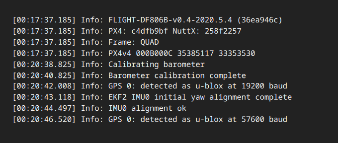
New board from stupid vendor.
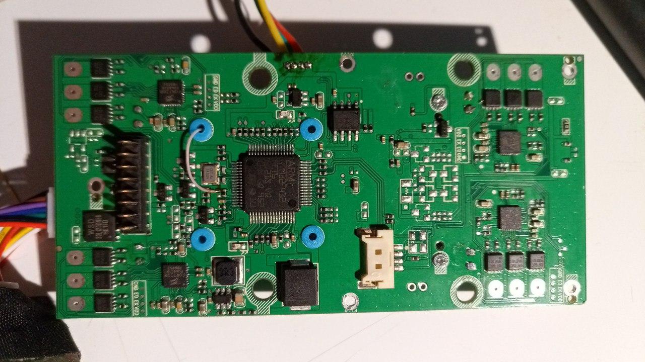
STM32F405 -> STM32F412 and fresh codebase
ROM:080797A4 0000007B C /home/yang/test_hardware/test_hardware_f806B-v0.5-2020.5.12/ardupilot/modules/PX4Firmware/
full firmware dump, useful if you have clean stm for replace
v2.5_stm32f412ret6.bin (512 KB)