Hello everyone, I am happy to say that some of the gear required for the mover has come.
Current gear list :
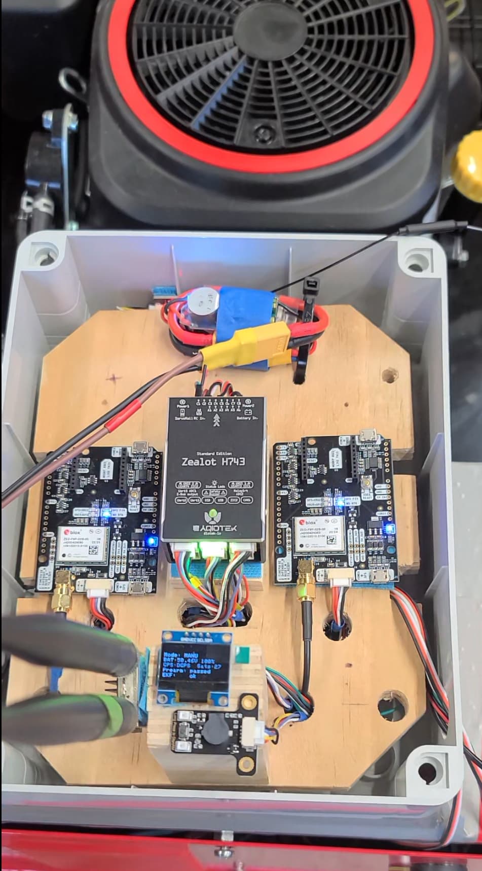
Orange Cube+ standard set
Two HiTec D845WP Servos
SiK Telemetry Radio V3
Flysky fs-i6x 10 CH Radio
I will try to start mounting servos to my mower to be able to drive it manually with the remote. My question now is maybe for Christopher because my mower doesn’t have an automatic starting system and so it doesn’t have a battery. I want to ask what battery, fuses, dc-dc converters, and all other electronics to buy. Also maybe if you have any wiring diagrams for connecting and powering all electronics that would be much appreciated.
After this conversion is done I will purchase Gear for GPS.
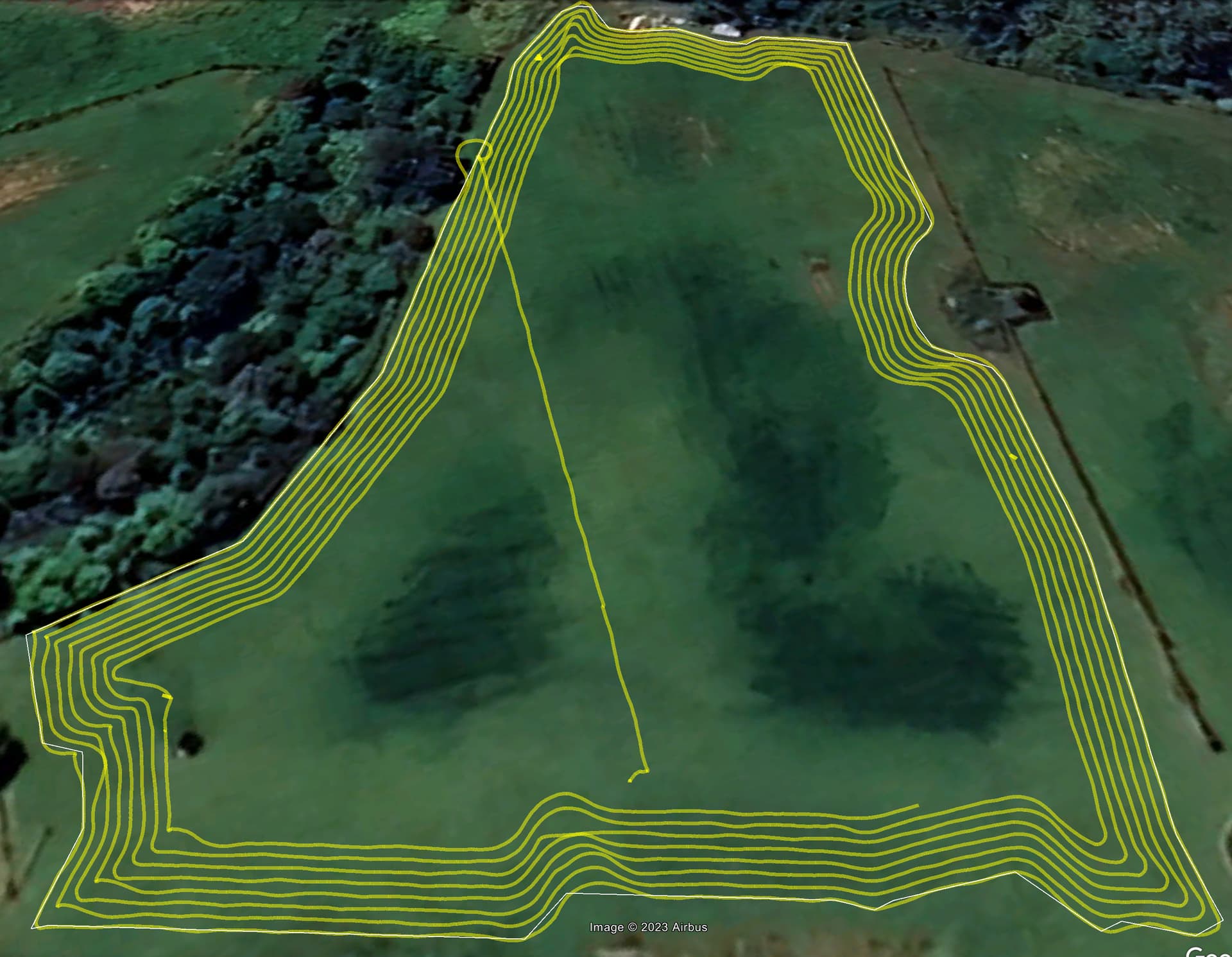
First paddock worked - the mower has an 800mm (31.1/2") cut width, i made a 0.78m flight plan, so any errors stand out, mostly good but a long way from all good. I was slightly surprised when i loaded in 850+ waypoints into the FC without any drama. The mower is slow - 0.7m/s and that was the biggest learning, need to run RC gear, laptops for extended durations… 4hours + for a large paddock, full fuel tank etc.
Failsafe’s all passed their tests - which is good because chasing a runaway mower sounds like no fun.
I suggest you start by sketching out your electrical subsystem. Draw the components and how they connect to each other. Draw both power (+12, +5, GND) connections and the signal connections. I suspect this diagram will have some or all of these components on it.
Main battery
Main power switch
DC-DC converter to power 5v electronics
Autopilot
GPS Boards
Companion Computer
Servos
RC Receiver
Telemetry radio
I myself wouldn’t worry about fuses for this particular set of components. You don’t have high voltage or high current.
(I’m not familiar with your servos. Do they take a +12v power rail and also a standard R/C PWM input as output by most autopilots? Others on this thread know the answer to this.)
I don’t know where to start but it seems like choosing a battery to power your electronics would be a first step. A small 12v 5Ah SLA battery would be something to consider. Mighty Max 12V 5Ah F2 SLA Replacement Battery for Trailer Break Away Kit 29483661140 | eBay
It’s old school technology but it’s cheap, non-spillable, probably available, and compatible with DC-DC converters or (BECs - Battery Circuit Eliminators - the same thing). You also have to figure out how to charge any battery you put on there and a pull start mower probably has a limited charging system. I wouldn’t expect a battery like the one I mentioned to reliably last more than 3-4 hours max without recharging when running all the electronics and servos.
Those HiTec D845WP servos will operate between 4.8 and 7.4 volts. The higher voltage will give you more torque and operate quicker. I have found that on my mower I get away with using 5V on the servos and it works for me the way I use my mower. If you went with some kind of LiPo battery pack you could probably arrange the wiring to run the servos straight off the battery back and no DC-DC converter would be needed for them. I am not familiar with all the LiPo battery options, but I would expect others would be able to offer comments.
It is important to note that you never want to try and power the servos and the other electronics from the same DC-DC converter. The servos can draw high current at times and cause voltage drops that can cause the flight controller to reboot (not good). I have a 10 amp fuse on the 12V side of the DC-DC converter going to the servos. The other DC-DC converter going to my electronics has a much smaller fuse (1-2 amps).
I’m working on a new mower too, trying to utilize a relatively new module, UM982 from unicore that has GPS YAW built-in. However, I’m facing some issues as described in Building a rover/mower, UM982 GPS RTK inaccuracy
Now, I’m not sure if going for a newly released hardware, UM982 in this case, is a good choice. It seems the route using ZED-F9P has been well proven.
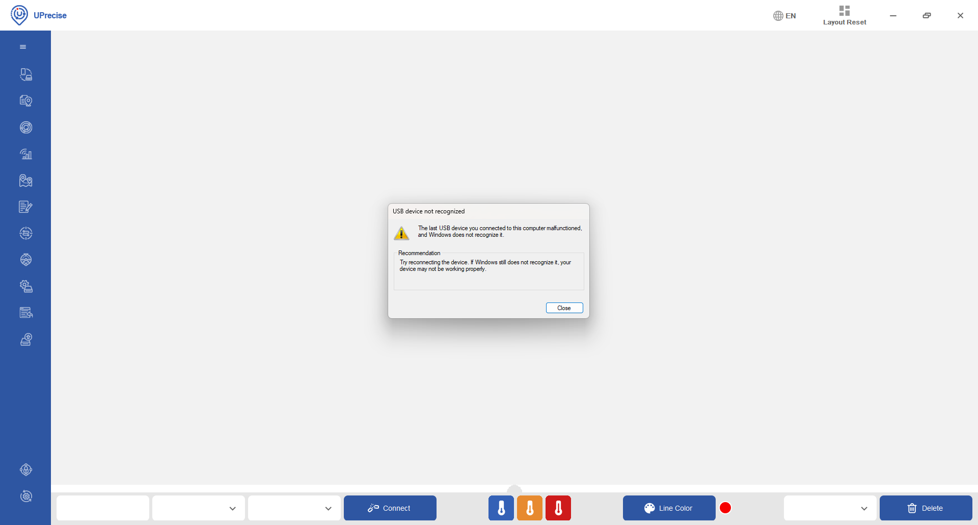
To further narrow down the source of the GPS position floating. I plan to use the UPrecise software to connect to the UM982 and manually turn the rover and see if the reported position floats. This is to rule out the possibility that ArduPilot is not configured properly on my side.
However, a new problem is blocking my plan. When connecting UM982 to my PC, windows doesn’t recognize the device and I can’t find a place to download dirver.
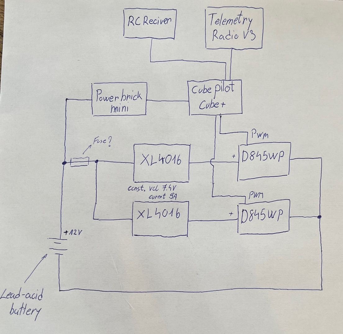
I think I will go with a lead-acid battery because I have one already. Do I need some sort of battery management system for lead acid batteries or not?
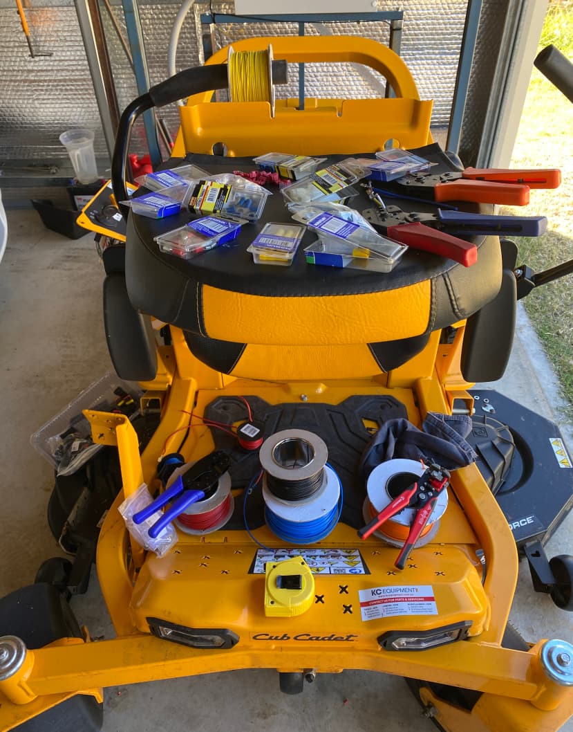
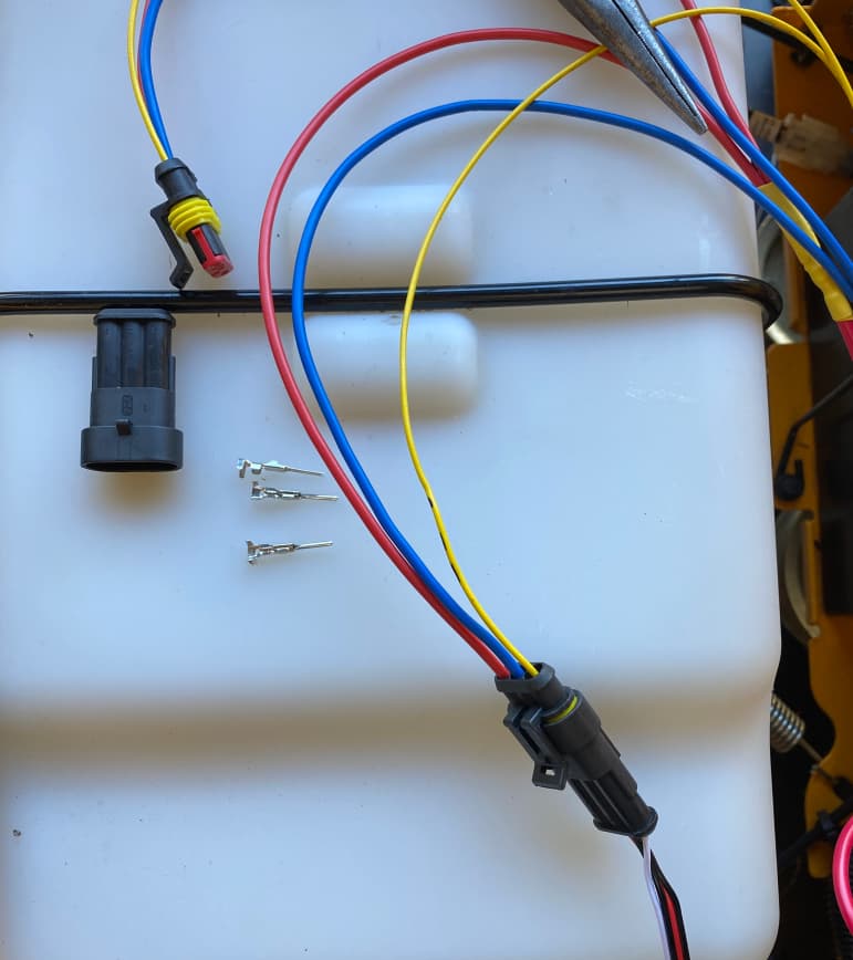
also, I was wondering what electrical wire diameter i need for connecting everything.
I like your diagram and it is basically correct except that you can power both servos off of the same DC_DC converter and the grounds for the mini DC-DC converter and the bigger one will need to be tied together for the signals going to the servo to have a ground path.
Here is a copy of a wiring diagram I put together to help out other builders. The intent was to try and put it in the Wiki mower building information set being assembled. Be especially careful with power wires and grounds. This may get altered as I get comments. it does work though and it reflects how my mower is wired. Cube mower layout 061023.pdf (546.0 KB)
If you don’t have a charging system on the mower for your battery system you will have to charge the batteries before you start with an external battery charger and have enough batteries to last until you are done.
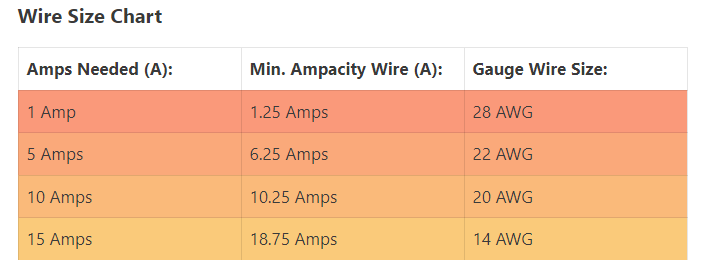
You will find that you will need several different wire sizes. You can always use a bigger wire than you need except that if you are installing connectors you need the correct size to fit in the connector.
If you put a 10 amp fuse on the larger DC-DC converter you would need 18-20 gauge wire. For the other wire suppling power to the cube the size is much smaller.
Yuri once wrote: “It is imperative that the rover and moving base communicate directly with one another, with the moving base providing RTK injects directly to the rover using the boards’ built in UART 2 ports. The flight controllers do not provide enough bandwidth/processing time for those injects to be passed through the controller successfully and at a high enough rate to support GPS yaw.”
Is this still the case?
Or does the ArduPilot auto-config take care of it?
My demo of a functioning servo-driven hydro-stat has to wait, as the 3D-printed parts simply broke after hitting the physical stop on the hydro-stat.
I have to admit that 15% infill was a bit flimsy to begin with and stupid at the same time.
Today I connected all my gear to the testbench. I got all 10 channels on my FrSky radio showing in mission planer I also connected Sik radios and servo. Servo is moving fine, my question now is what is the best way to arrange controls for skid steering on my transmitter?
My DC-DC is able to draw 9A is this really enough for two D845WP servos or do I connect every servo to one DC-DC?
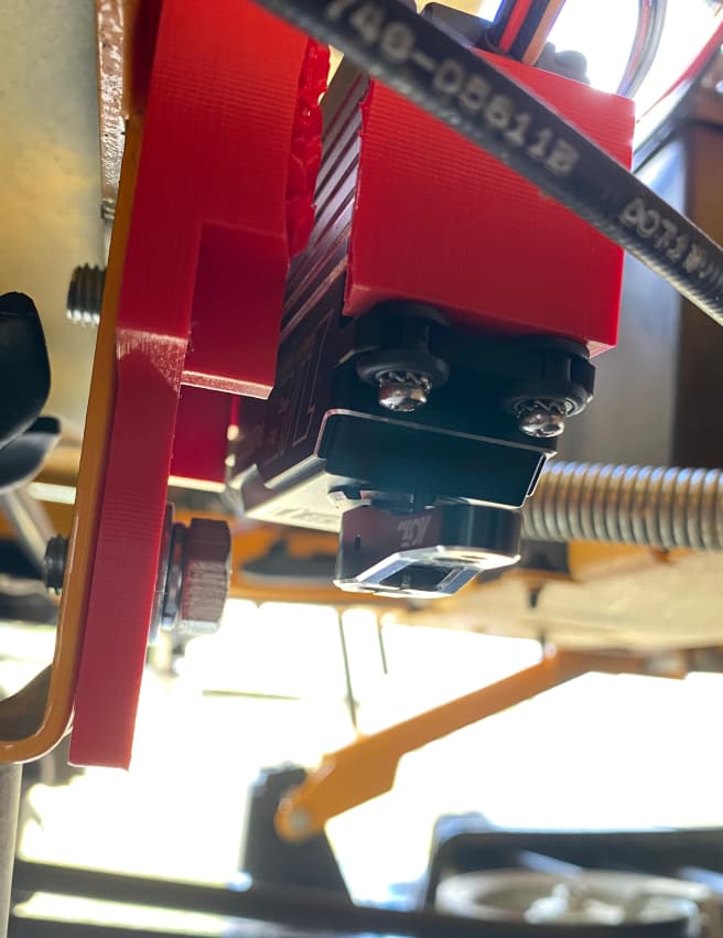
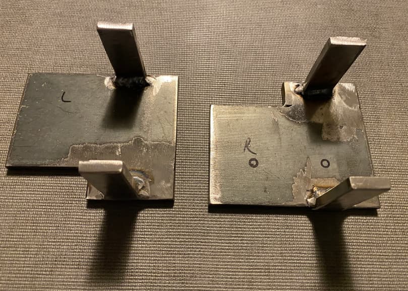
Servos mounted, ready for calibration and configuration.
I am using Yuri’s post: Yuri's 4.1.0-beta Update (GPS yaw - now 4.3-beta1) - #130 by Yuri_Rage to get this sorted, and repeat here the steps in order, though for a new system. However, this might be wrong, and I will update this post based on feedback to get it right for others to follow.
use Servo Output page under Setup in Mission Planner to set the end stops by visually observing the PWM value where the plate was at full travel
Set-up all of the SERVO1* and SERVO3* PWM parameters [after a linkage change/adjustments].
jack up the mower up and start the engine to roughly set the trim values to neutral (no wheel movement)
fine tune the trim values using @ktrussell’s wheel tracking method 3, where you put a piece of tape on each wheel (still jacked up off the ground), push the RC stick forward in manual mode, and tune the trim values up or down to achieve the same wheel speed on each side.
tune the throttle and steering parameters
Don’t underestimate the importance of CRUISE_THROTTLE! Set it first and get it right (or undershoot slightly)
Once the throttle is tuned, move on to steering. Ensure lack of free play in the linkage system. Slightly increase the FF gain
move on to pivot turn tuning, mostly adjusting ATC_STR_ANG_P in small increments until the mower nails the heading on each turn.
When things are looking pretty good, fine-tune the WP_RADIUS parameter to ensure that the mower pivots as close to the actual way-point position as possible.
set the ATC_ACCEL* and DECEL* parameters about as aggressive as possible
changing WP_RADIUS is the mechanism to ensure pinpoint turn precision. Too small a WP_RADIUS can have ill effects in way-point navigation, so be careful setting it too low (or zero). I ended up at 0.43m.
With the mower turning almost exactly on top of each way-point, dial in ATC_STR_ANG_P so that it exits every turn with minimal under/overshoot.
Lastly, check how the GPS_POS* and INS_POS* parameters might help or hinder things.
Take some careful measurements, referencing the rear (drive) axle center line, which should be the pivot axis. The GPS antennas may only be about 2" aft, nevertheless enter a negative X offset to account for that. If the flight controller is almost in front of the rear axle, enter a positive X offset. Entered a negative Z offset for the GPS antennas, if they are say 2 feet above the flight controller. The result will be quite interesting!
Re-tuning the steering parameters slightly might be necessary, to reduce overshoots.
(Commentary: It appears that things are dialled in so closely now, that I can determine that the mower doesn’t do perfect pivot turns. It looks like the outside wheel travels a little farther than the inside wheel, making a little diagonal trace on each turn I’m curious to see if I can bias the servo trim a little toward the reverse direction and get even closer to perfect.)
What other setting need to be set, configured or tuned?
Does the above contain all steps?
Is this order correct?
I think the single power supply will work fine. Normal operation should be well below the max of your power supply.
You need to be going through all the setup documentation in the Wiki documentation labeled First Time Setup. In there is a section on motor and servo configuration. https://ardupilot.org/rover/docs/rover-motor-and-servo-configuration.html
In that section it tells you that you have 2 options that will work for rovers like the mower. One is for separate steering and throttle vehicles where the left joystick on your RC transmitter will control throttle and the right one will be the control to turn left and right. It is also possible to modify this first approach to drive the mower off one joystick where left-right is steering and up-down is throttle forward and reverse.
The second approach for “Skid steering” vehicles and the left joystick controls the left drive wheel forward or reverse and the right joystick controls the right drive wheel forward or reverse.
All of these are personal choices and you see people doing different things. I elected to configure mine to separate the steering and throttle where the left joystick controls throttle (which also controls forward and reverse) and the right one controls to turning left and right. Now that I understand this better I will probably be changing mine to be on the same joystick someday just so I can drive with one hand.
If you don’t complete all the stuff in first time setup you will have trouble and be eventually circling back to get the stuff done so things will work.
I would suggest that after the first 3 steps in your list above were done you need to start going through the First Drive and Tuning section of the Ardupilot Wiki set. https://ardupilot.org/rover/docs/rover-first-drive.html
There are numerous parameters that need to be set associated with many things. There are things that need to be done before you can move to specific tuning parameters, which are also covered in that section with detailed instructions and videos. Even the guys who have done this before reference back to that detailed instruction set to tune their mowers.
The post you quoted is 2 years old and was conversation between the experts who helped perfect how to do this and write the Wiki set on tuning.
I wouldn’t call the referenced post irrelevant or overcome by events, even after a couple of years. But Steve’s advice to simply follow the wiki is well said. Get the basics first. Fine tune from there with the “advanced user” parameters if results are unsatisfactory.
On the contrary, any forum discussion regarding moving baseline woes that dates back more than 6-9 months is probably outdated. Follow the wiki and be done with GPS-for-yaw config.