Thanks Kinzo. So what numbers are this command? they should be 16 numbers. But what are the numbers? In this Format : 42 57 02 00 00 00 00 00
NO,that can’t be 16 numbers. and TFmini and TFmini Plus are different sensors.
Thanks Kinzo, I get it now. I will give it a try.
Anyone know who is selling th eTFmini in the I2C version. I checked Sparkfun and they have the the TF Mini but it has some add on board.
Cheers
I send the code 5A 05 0A 01 6A to TFMini Plus and is dead now…cant see anything on GUI.
Sparkfun’s add on board does nothing for i2c protocol, it is just a power management board that can be ignored. I have their i2c TFMini and it works good (not with arducopter).
Thanks All.
I will get one ordered.
cheers
Ok I ordered and have received the I2C version of the TF Mini. Is there anything special one needs to do to make it work with Arducopter.
After doing some reading I found that I had set the Rangefinder type to the serial version. I corrected that to the TFMini I2C and now get the message that the rangerfinder is not detected. So this is a positive step I am now getting an error…But the down side is…Now I am getting an error. I suspect its an addressing issue…but I am unsure what to set it too.
In another document I just found this statement…hmmmm. However in the product manual it makes no statement of TTL only that its I2C.
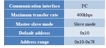
The default communication of TFmini Plus is TTL,IIC and TTL are same cable,so please set TFmini
Plus to IIC communication first,see detail commands in product manual.
But when I connect my USB to TTL adapter as I did for the UART TFMini there is no data received from the Lidar making me think its really talking I2C.
I connected it direct to the pixhawk bypassing any I2C hubs just to make sure power from the Pix wasn’t a problem…no change.
I really think it’s an address issue but I am at a loss to understand what.
I read in one document to set RNGFND1_ADDR=16 [Address of #1 TFmini Plus in decimal]
But I have no idea if this is correct as the document speaks to using it as a proximity detector for avoidance.
I also confirmed its not a power issue by running the TF on it’s own bec. Pain to setup but I did it…no change.
This is the address which i believe is 16 if I convert it from hex to decimal.
1 Like
hi rickyg32, there is a github repo for setting the address using an Arduino. Please check it out:
Hope this helps!
Thank you @Mahathi1992
The issue turned out to be a version of the TF Mini that isn’t compatible with ARducopter. So I replaced it.
Thanks again its really appreciated.
@ppoirier
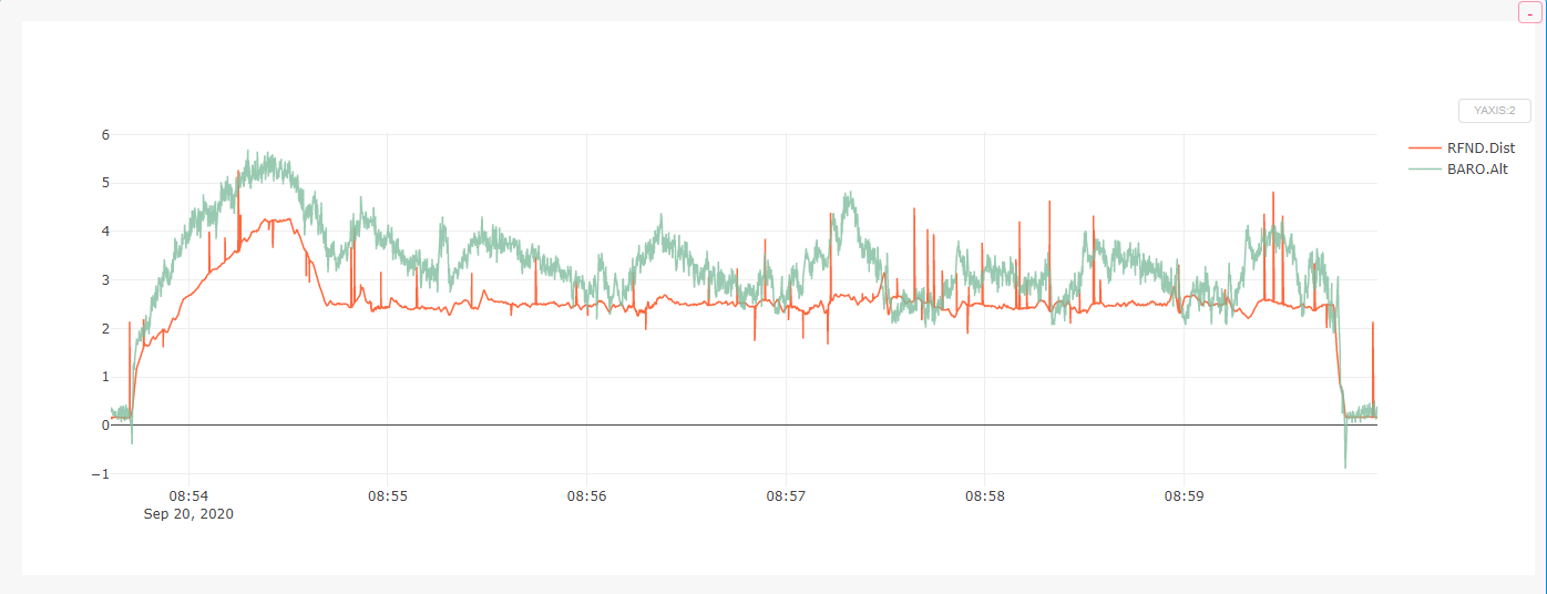
Anyone know what causes the spikes in the Lidar distance measuring.
I am using a TF Mini Plus on Pixracer. It’s powered independently.
Just find it odd, doesn’t appear to affect the copter performance but since it’s a new build I am looking for potential issues.

This is the same with baro overlay.
Ricky on what bus , I2C or Serial?
Ah shoot should have mentioned that. It’s I2C
Well, in that case you can switch to serial to rule out driver or interfaces issues.
I didn’t think there was a way to go back to serial. Also I would need a uart port and they are scarce
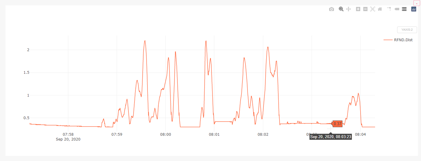
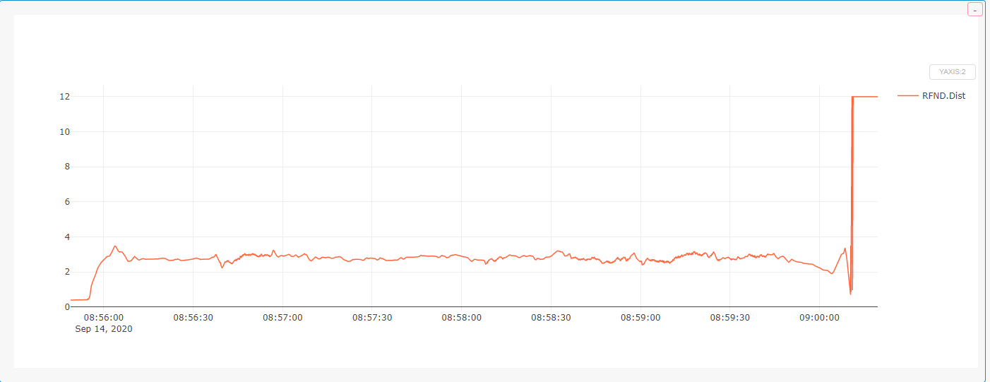
These are the graphs from the other two drones with lidar
Serial
I2C
I wonder if it’s a power issue. Not enough juice causing some kind of spike, or noise on the line. Will investigate.
1 Like
Try loading the I2C with lower values ( 1 K) pull-up resistors on Clock & Data lines
You mean a 1k to 5v.
What are you thinking. Let me rephrase that…Why do yo think there would be a benefit to doing that.
I2C lines must be loaded with pullup resistors, maybe there is a problem with TfMini loading and you can force it with external pullups.
Ok. Never ran into that before but easy enough to do. Just pull up to 5vdc is that correct.