Yes correct (and more characters)
@xfacta Sometimes I just cant’ tell if your pulling my leg or trying to teach me something.
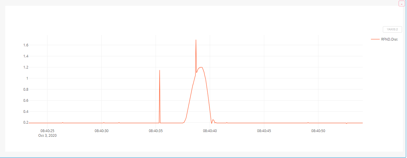
So I am holding off on the pull up resistors just yet. I made a change to how the Lidar is being powered. I want to rule out one thing at a time. I have seen these spikes in other systems on this and other quads and they where power related…I just found it odd on this machine as the lidar was powered separately …but want to check that first.
Never pulling your leg - I’d like to think my jokes would be a bit more obvious  I just had to type more characters in that last post. It’s rare for me to not write more of a story.
Adding pullup resistors wouldn’t be detrimental except for the extra work involved.
HAHAHAHA
ya I get it now. I guess my approach to the items in the forum are taken to serious I miss the funny. lol
So confirmed the change to the power supply had no effect on the spikes.
Next will be the pull up resistors.
Ok So I added the pull up resistors. I was sure that when I powered it up the I2C buss wouldn’t work. That the Lidar would stop and the external LED would not flash. But I was wrong.
I checked everything out and it’s all working as expected so this week sometime I will get her airborne again and see how the lidar performs. See if those spikes still exist.
Pull up resistors…one of life’s little mysteries.

It’s written on the package == Outstanding Protection !!! … it must be true 
2 Likes
hahahah smartie.
There are days when I fly drones I could use adult size lol
1 Like
I think the spikes are filtered out before using them for height estimates anyway. It should not affect flight performance. I had similar issues with SF11c lightware lidar. Though it wasn’t so many spikes.
Yes I agree that they are filtered out and not a problem on the machine its self but they are there and it’s just one more thing to potentially cause a problem so if I can knock it down I shall.
This was just a quick up and down but the pull up resistors appear to have no affect on the lidar data.
1 Like
Hey out there.
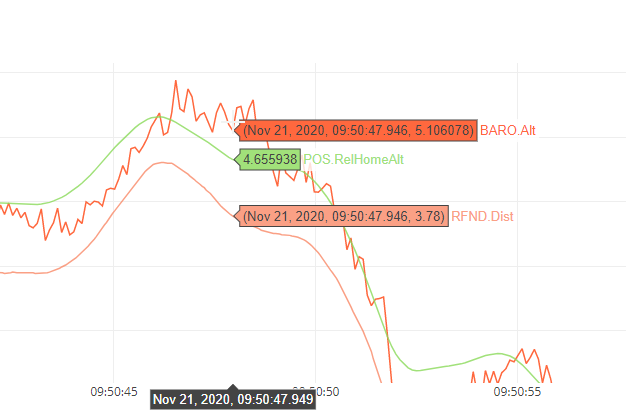
Can anyone give me a hint as to why the TF mini and Barometer would be so far off on altitude.
I dont’ have this on any other drone…they are generally pretty close.
Also on another quad I notice that the distance from the ground is 26 yet the ground clearance is 31 and the minimum distance is 30 so where does 26 come from. Is it because it’s sitting on grass perhaps.
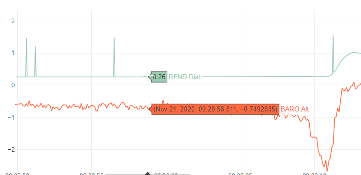
This drone shows the correct distance. .3 sitting on the same grass
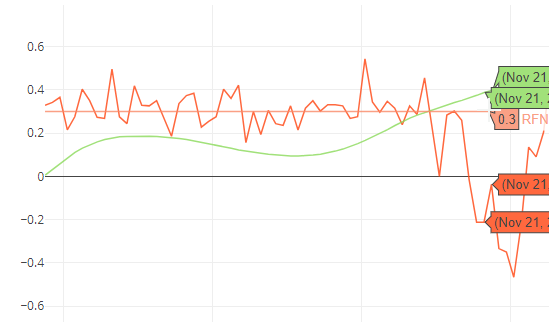
Also I thought the barometer Zeros out when armed on the ground…Setting the home altitude. If this is the case why would this be a negative number.
Hi Siya,
Thanks so much for your prompt response. I was able to use budryerson’s Arduino library to change the I2C address. I had to change the baud rate in Arduino IDE to 115200 to get the code running properly, a noob mistake ![]() (57600 baud rate for running the example code “I2CChange” was showing me gibberish in the serial monitor upon running the code.) Big Shout out to Bud Ryerson!!! And to Arduino community to help us noobs
(57600 baud rate for running the example code “I2CChange” was showing me gibberish in the serial monitor upon running the code.) Big Shout out to Bud Ryerson!!! And to Arduino community to help us noobs ![]()
I have also seen wonderful posts from Ibrahim Qazi. The ones I saw addressed UART/Serial port connection for TFMini Pus. Thanks Ibrahim, please keep writing the posts, especially for I2C bus as it seems easier to daisy chain the I2C sensors using the i2c splitter provided by Pixhawk vendors.
I will reach out to the support to get the Benewake Upgrade tool to keep the firmwre on my Lidars updated.
I am moving on to the next step now to connect the 2 Lidars to my Pixhawk 2.4.8. From reading the very thorough posts in this forum, I understand that the lidars need to be connected to 5V BEC. That would be a new challenge as I have not connected to devices to the same 5V BEC.
Thanks once again!!
Hi Asim, thank you for your questions. I’ve invited our engineer Ibrahim for help. Or you are also welcome to send email to support@benewake.com, our engineer will reply. Thanks.
Hi Siya,
Thanks so much for your prompt response. I was able to use budryerson’s Arduino library to change the I2C address. I had to change the baud rate in Arduino IDE to 115200 to get the code running properly, a noob mistake ![]() (57600 baud rate for running the example code “I2CChange” was showing me gibberish in the serial monitor upon running the code.) Big Shout out to Bud Ryerson!!! And to Arduino community to help us noobs
(57600 baud rate for running the example code “I2CChange” was showing me gibberish in the serial monitor upon running the code.) Big Shout out to Bud Ryerson!!! And to Arduino community to help us noobs ![]()
I have also seen wonderful posts from Ibrahim Qazi. The ones I saw addressed UART/Serial port connection for TFMini Pus. Thanks Ibrahim, please keep writing the posts, especially for I2C bus as it seems easier to daisy chain the I2C sensors using the i2c splitter provided by Pixhawk vendors.
I will reach out to the support to get the Benewake Upgrade tool to keep the firmwre on my Lidars updated.
I am moving on to the next step now to connect the 2 Lidars to my Pixhawk 2.4.8. From reading the very thorough posts in this forum, I understand that the lidars need to be connected to 5V BEC. That would be a new challenge as I have not connected to devices to the same 5V BEC.
Thanks once again!!
Hi Asim, glad to know your progress. There are many talents here that sharing many interesting and valuable posts/documents, that’s really great.
For other issues, you can also @ibrahimqazi for help.
Thanks Kindly Siya! Stay Well.
Hello dear Asim,
Thank you for nice words. We will try to provide more relevant materials as much as we can.
If you have any questions, please let us know.
Wassalam Dear Ibrahim,
Thanks for your message. If you have any advice for any easy connectors for connecting two or more TFMini Plus, then that would help. There is a lot of discussion about that in this forum.
I am currently studying @ppoirier wonderful post below for the connection. I am looking forward to learning to use the breadboard. Once again, thanks for all your support.
1 Like
My suggestion is either remove current JST connector and buy 6 pin JST connector if you are using UART interface of your flight controller. Or if you are using IIC interface which is 4-pin then you don’t need to remove original connector, just use an extension board which has compatible mating connector for JST connector of TFmini-Plus, and pay attention to SCL and SDA lines. It should work.