ArduRover on real competition R/C 1/10 car on real circuit: missions. FAR FROM WORKING

Hi.

I am trying to emulate on an ArduRover missions working on an Arducopter over a real R/C circuit. The car is a competition 1/10 one (with steering servo and ESC), although I start limiting throttle pulse width on the controller (SERVO2_MAX=1580), although this can be done as well on the transmitter.

Transmitter used is a Futaba T3VCS three channel radio. Steering (ch1) and throttle (ch2) are assigned normally, and ch3 on a knob is used to change mode. Note that since I don’t know to arm the rover with a ch1+ch2 sticks combination, the rover is always armed (ARMING_REQUIRE=0).


I use Mission Planner as GCS. Car controller is a clone Pixhawk v2.

As examples of missions to emulate (Copter) over the real car R/C circuit:
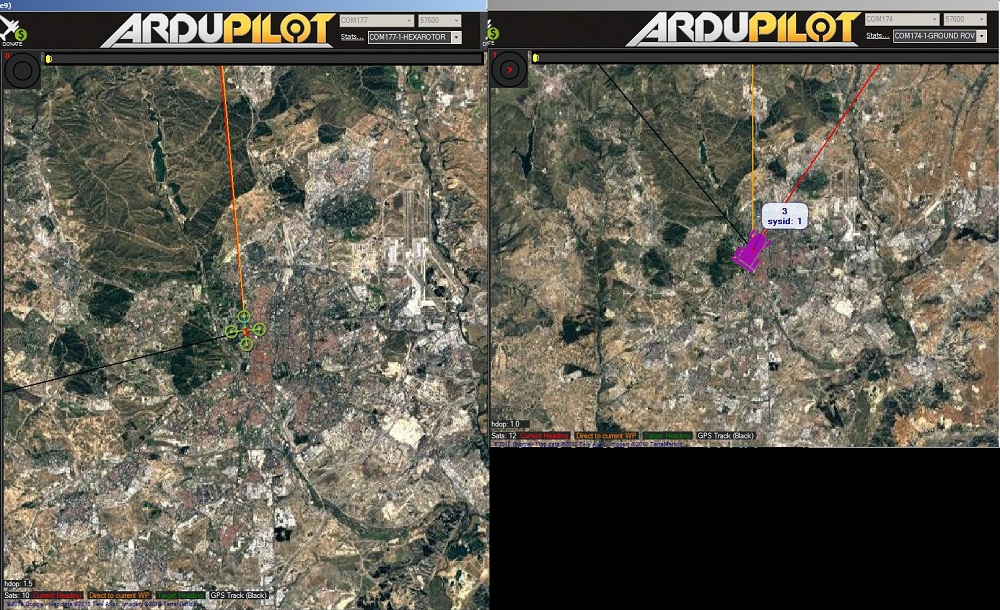
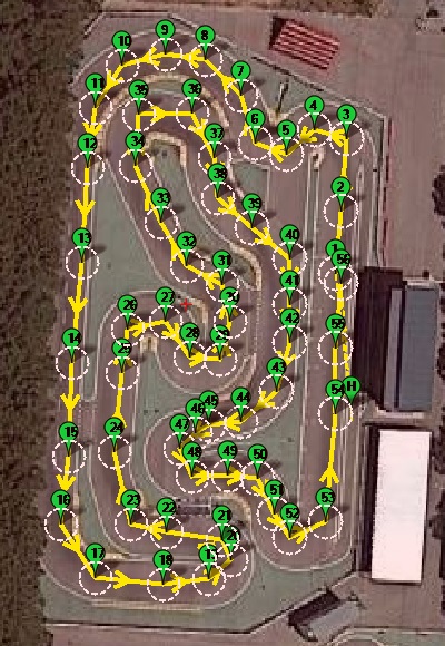
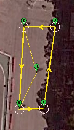
Example 1 mission drone
Example 2 mission drone

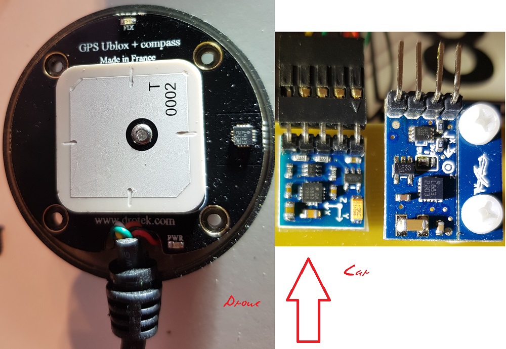
Drone controller is also a clone Pixhawk v2. Transmitter is a Futaba T7C and receiver is a FrSky TFR4-B, with PPM output (no PPM Encoder needed). It has two GPS’s; first one has a 5988 compass (external one). I try to use same electronics and configurations on the Copter and Rover. Drone and car communicate with GCS with 3DR radios.

The car receiver is a Futaba R603FS. Its outputs are connected to a PPM Encoder: ch1 and ch2 normally, and ch3 to ch5. On the controller MODE_CH=5. The PPM Encoder output is connected to Pixhawk PPM input. Pixhawk main outputs 1 and 2 are connected to car steering servo and ESC.

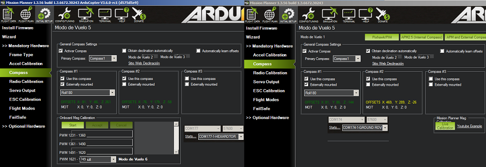
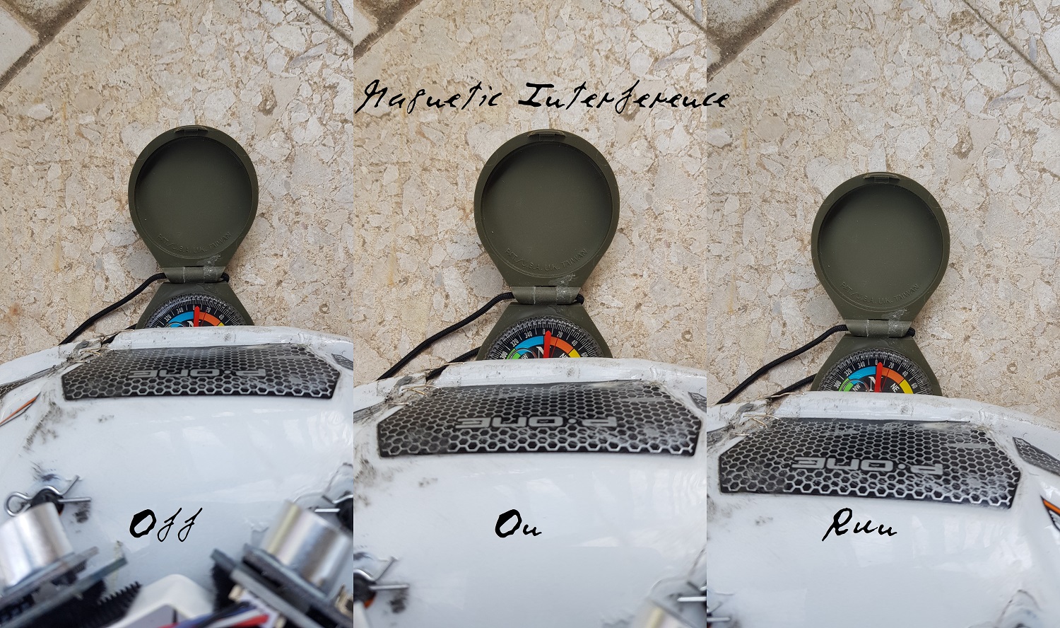
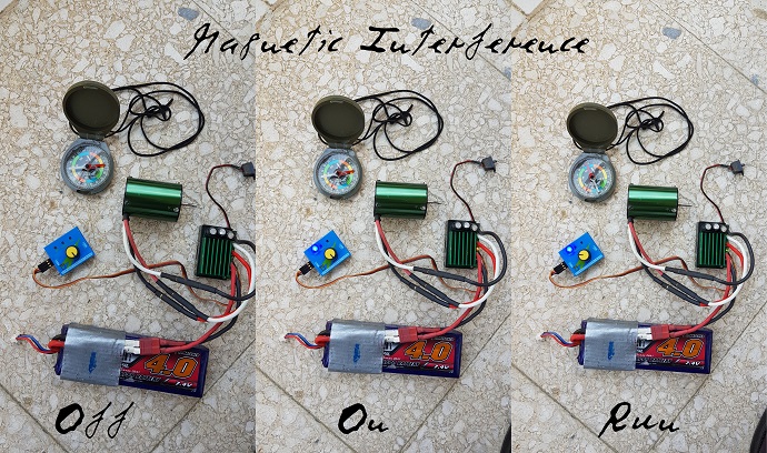
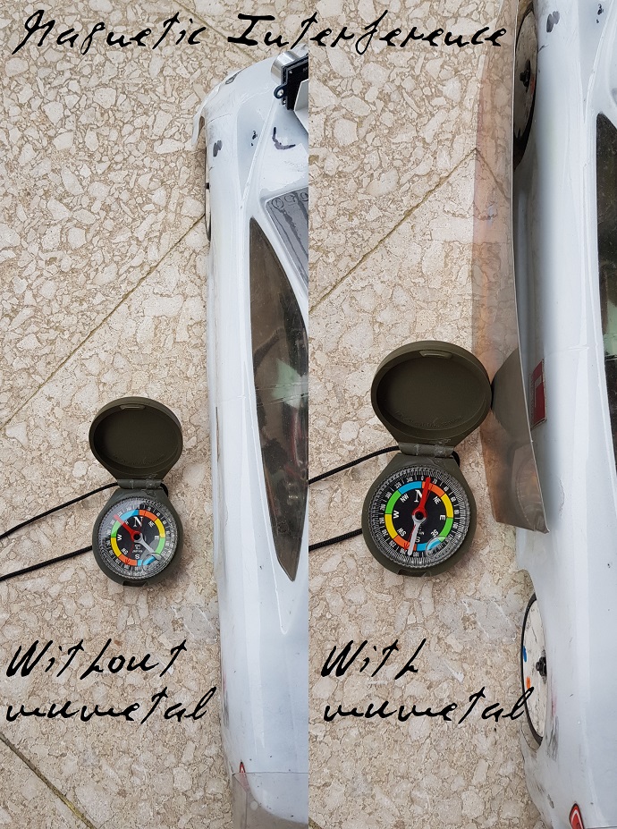
The car Pixhawk has connections to two GPS’s. GPS1 has a LIS3MDL compass; for whatever the reason it is not recognized, so I don’t connect its I2C SCL/SDA signals and use instead a module with a 5888 compass (external), with its dot oriented front-right (Roll180), the same as in the drone. Second compass is the Pixhawk one (internal), the same as in the drone.

The car has also two sonars at the front (chinese analog and I2C, both with HC-SR04).

The steps for making everything work would be:
1). Basic car movement (modes Normal, Acro and Steering). Works (latency is clear in car handling).
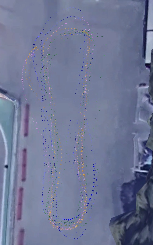
2). Guided and Auto modes (compasses and GPS’s working; missions). FAR FROM WORKING.
3). SmartRTL mode.
4). Sonars (front obstacles avoidance).

If missions work, speed would be increased, and accelerometer lateral measurements would be used to reduce speed as needed, so as to improve lap time.

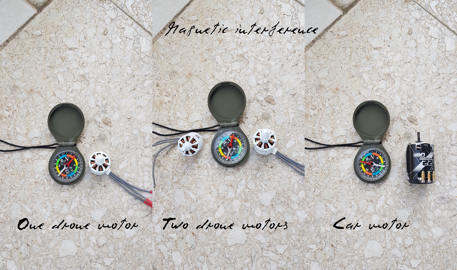
But I am completely stuck at 2: nothing works, and is really far from working. For example, on Guided mode the car turns and goes opposite to desired point. This sounds as a compass problem, but:
-Compasses (external and internal) are almost the same in drone and car.
-I copy the configuration on drone and car (same external one orientation, (Roll180)).
-Calibration on drone and car succeeds (both external and internal compasses).

Sounds as if rover doesn’t know how to translate desired actions towards the steering servo for whatever the reason.

Questions:
-Am I missing something?
-Any wrong or missing parameter below?
-How can I start to make Guided and Auto modes to work?

Any help deeply appreciated. Thanks for reading.

GCS messages:
EKF2 IMU0 in-flight yaw alignment complete
PX4v2 004B0036 3436510A 32393637
PX4: fc469199 NuttX: 1bcae90b
APM:Rover V3.2.3 (261f998f)

Relevant parameters:
AHRS_EKF_TYPE,2
AHRS_GPS_USE,1
AHRS_ORIENTATION,0
ARMING_REQUIRE,0
BTN_ENABLE,0
COMPASS_EXTERN2,0
COMPASS_EXTERN3,0
COMPASS_EXTERNAL,1
COMPASS_ORIENT,8
COMPASS_ORIENT2,0
COMPASS_ORIENT3,0
COMPASS_PRIMARY,0
COMPASS_TYPEMASK,0
COMPASS_USE,1
COMPASS_USE2,1
COMPASS_USE3,0
CRUISE_SPEED,2
CRUISE_THROTTLE,50
EK2_ENABLE,1
EK3_ENABLE,0
FRAME_CLASS,1
FS_ACTION,2
FS_CRASH_CHECK,0
FS_GCS_ENABLE,0
FS_THR_ENABLE,1
FS_THR_VALUE,910
FS_TIMEOUT,5
GCS_PID_MASK,1
GPS_TYPE,1
GPS_TYPE2,1
INITIAL_MODE,0
MAG_ENABLE,1
MODE_CH,5
MODE1,0
MODE2,1
MODE3,3
MODE4,4
MODE5,10
MODE6,15
PILOT_STEER_TYPE,0
PIVOT_TURN_ANGLE,30
RC1_DZ,30
RC1_MAX,2014
RC1_MIN,1008
RC1_REVERSED,0
RC1_TRIM,1545
RC2_DZ,30
RC2_MAX,1906
RC2_MIN,1049
RC2_REVERSED,0
RC2_TRIM,1511
RC5_DZ,0
RC5_MAX,1970
RC5_MIN,1069
RC5_REVERSED,0
RC5_TRIM,1340
RCMAP_PITCH,3
RCMAP_ROLL,1
RCMAP_THROTTLE,2
RCMAP_YAW,4
RNGFND_TYPE,1
RTL_SPEED,0
SERVO_RATE,50
SERVO2_MAX,1580
SPEED_TURN_GAIN,50
TURN_MAX_G,1
TURN_RADIUS,0.9
WP_OVERSHOOT,2
WP_RADIUS,2
WP_SPEED,0

Rest: moreless default.

1 Like

Webillo,

Thanks for the detailed post.

Normally the COMPASS_ORIENT should be 0 instead of 8 (Roll180) although it could depend upon the GPS/Compass manufacturer.back in the old APM days Roll180 was required but with the Pixhawk family it’s normally zero.

I think it would be good to disable the range finders (set RNGFND_TYPE 0) until we get Guided or Auto working properly.

Two possible causes come to mind:

  • the compass heading is off. If you connect with the MP and look at the map, does the vehicle appear to be pointing in the correct direction?
  • the SERVO1_REVERSED parameter is backwards.

If you can download an post a dataflash log (a .bin log) then I can have a look and see what’s going on.

Thanks for giving Rover a try!

Thanks for your answer.

Pixhawk mounting on both is normal (arrow forward).

These are the external compasses on both drone and rover:

External compasses chips are 5883 or 5983, and are oriented equally (as seen I’ve tried two compasses on the car with same results). Dot is at front-right (I think Roll180). All point to sky (see that at the drone it is at the GPS antenna PCB side).

This are compass definitions on Mission Planner (same):

Everything works well on the drone, but a static test with both parallel and facing north gives:


Good on drone but far from good on rover.

¿Does dot at front-right and chip upwards for external compasses correspond to Roll180? If not, why everything works on the drone (PosHold, Auto, RTL)?

Now I have SERVO1_REVERSED=0; steering stick to right makes car turn right. If changing to 1 steering is reversed (not good). Of course, transmitter in normal position (sticks facing me).

I don’t mind now about the sonars; in fact I have tried with both disabled and/or disconnected.

I am sure I have a big error somewhere. What can I log that could show it?

Ok, this is a classic compass. I haven’t seen one like that in years. These days the compass is normally included in the GPS module. In any case, nothing wrong with using this hardware - it should work and the Roll-180 could indeed be correct.

The heading being off by 45degrees is not as bad as I was expecting. 45 degree error shouldn’t cause the rover to drive in the wrong direction. This 45 degree error could be caused by having metallic parts near the compass, a bad compass calibration or the EKF’s heading estimate can be incorrect if the rover is carried around a lot before it is driven (we have a software fix coming for this last issue).

If you have a dataflash log that would be best. In particular I want to see the STER (steering) and THR messages. From the STER message, the desired and achived turn rates are most interesting.

Thanks. I’ll try to do the logs next Sunday.

Recall that I am using the internal and an external compass on both drone (inside GPS1) and car (small separate I2C module, since it GPS1 LIS3MDL isn’t recogniced (I have tested it with an Arduino and it works)) Pixhawk’s. For internal ones COMPASS_ORIENT2=0 (Pixhawk’s oriented as their arrow indicate, AHRS_ORIENTATION=0). I have looked at the internal drone compass. It has written on it 303H, so it should be a LSM303DLHC (ST Microelectronics). It is facing down, opposite to connectors side. If rolling it 180º its dot position is the same as the Honeywell 5883/5983 on external compasses photos above, so external COMPASS_ORIENT=8 or Roll180 for both (supposing same rules for Honeywell and ST).

However, I am always seeing car heading off, after several calibrations and testing in different places. Drone heading is always correct. On above screen capture (desktop captured using a laptop and an external monitor) the car was above the drone and parallel, so any magnetic distortion should affect both.

From above, car Manual and Auto modes work correctly, but on Steering mode steering is erratic: the steering servo moves slowly, steering angles are small, and the car is difficult to handle. Does this give any clue?

Magnetic Interference: probably this is why car orientation fails (and has a remedy).

This is how a traditional compass is distorted when it is near brushless drone and car motors (stopped):

Note that car motor has stronger magnets.

This is how a traditional compass is distorted when it is near a brushless car motor:

When the motor moves, the distortion is reduced on the average.

So the solution is clear: on the car don’t use the internal Pixhawk compass, and place the external compass (in the GPS or as an I2C small module (GY-271)) at the front bumper:

The distortion is hard to appreciate.

Also:
Magnetic Interference
CompassMot — compensation for interference from the power wires, ESCs and motors

Ok, thanks for the info. I think for now we don’t support the compass-mot on Rovers. It’s possible to add but not there at the moment.

Re the results in steering mode, definitely that log will help diagnose this. The first step is to determine if it’s a control problem or a heading estimation problem. It could be either …

1 Like

Hi.

Although placing the compass GY-271 I2C module on the front bumper, being it the unique compass which calibrated easily, and giving correct orientations, in Guided and Auto mode the result was the same, so a big error is still present.

In Guided mode, even having the car oriented to the destination point, the car turned and went opposite.

In Steering mode the car was handled better than before.

I got two .bin logs. Since they are too big (13MB and 38MB), better than uploading, here are links to download them:
Rover_201805200925_00000176.BIN
Rover_201805201032_00000177.BIN

Thanks for your review.

Here is another test of a motor near a traditional compass:
MagneticInterference_ServoTester_label_690x408

Wouldn’t it be better to calibrate the compass with the motor out of the car?

I don’t think the compass is the issue probably.

The SERVO2_TRIM value of 1517 looks very suspicious because SERVO2_MIN = 1000 and SERVO2_MAX = 1580. Do you know what the full range of the main motor’s ESC is?

The important questions to answer are:

  1. what PWM causes the motor to spin full speed backwards? <-- put in SERVO2_MIN
  2. what PWM causes the motor to spin full speed forward? <-- put in SERVO2_MAX
  3. what PWM causes the motor to stop? <-- put in SERVO2_TRIM

Maybe try using the mission planner’s Motor Test page to check that the throttle and steering are working?

Recall that the car is a real 1/10 competition one. At the beginning I used the transmitter full throttle range (Futaba nominal), but since Guided and Auto modes didn’t work I had several small accidents (the car was uncontrollable), so I limited manually the maximum speed (SERVO2MAX=1580) at the controller (could be also limited at the transmitter or ESC). The ESC is calibrated to the full transmitter throttle range 1000-2000 (if I take the Pixhawk controller out (receiver to servo and ESC) I can race with the car).

1517µs (SERVO2_TRIM) is Futaba nominal neutral pulse width at the transmitter (moreless). It is the pulse width with which a traditional analog Futaba servo would be mechanically centered exactly.

The transmitter throttle stick has a 7:3 range (set mechanically), although the neutral mechanical point gives mid pulse width (1517µs). There is no backwards speed (no reverse speed admitted on these competition cars), so the whole lower range (first 3/10 of the total range) is used for braking.

So the transmitter is calibrated to give:
-1000 to 1517: the car brakes (possibly ESC shorts two phases). SERVO2_MIN to SERVO2_TRIM.
-1517: car stopped (SERVO2_TRIM=1517).
-1517 to 2000: car accelerates. While in this tests, the Pixhawk controller output is limited to 1580 (SERVO2MAX=1580).

In the Motor Test page, Test motor A button tests car motor, whose speed depends on Throttle %. Test motor B button tests steering servo:
-Throttle % 0: steering servo centered, wheels centered.
-Throttle % 50; steering servo moves wheels half way to left (as if steering stick to left, pulse longer than neutral).
-Throttle % 100: steering servo moves wheels full way to left (as if steering stick full to left, pulse at max length).
Unless I miss something, right steering is not tested.

MissionPlanner_Rover_motortest

If observing chin’s and chout’s indications:
MissionPlanner_Rover_chinout

Here steering stick is centered (ch1in=1571, ch1out=1517) and throttle stick is at maximum speed (ch2in=1904, ch2out=1579 (speed limited at the Pixhawk controller with SERVO2MAX=1580)). Mode is selected with the transmitter knob, being receiver ch3 connected to ch5 on the PPM encoder, giving ch5in=1070 (Manual mode, being MODE_CH=5).

On the PPM encoder, channels 3, 4, 6, 7 and 8 are open, so they are open inputs. Strangely, ch4in=ch6in=ch7in=ch8in=1498, but ch3in=899.

Recall that I can handle the car normally (with limited speed) in Manual, Acro and Steering modes, although with appreciable latency. Guided and Auto modes don’t work at all all possibly because a big error, as if in this modes the controller would not “know” to command steering for reaching the desired point.

Webillo,

Ah, so if the steering moves left when using the motor test page then that means that SERVO1_REVERSED is incorrect. The steering is reversed which explains why the vehicle would drive in the opposite direction from where it was intended to go. Once you correct that you’ll probably find that manual doesn’t work anymore. the best way to fix this is by reversing the PWM direction in the transmitter, if that’s not possible then I think you can change RC1_REVERSED.

Hi. Thanks a lot. From the rover documentation:
RC1_REVERSED: RC reversed
Reverse channel input. Set to 0 for normal operation. Set to 1 to reverse this input channel.
SERVO1_REVERSED: Servo reverse
Reverse servo operation. Set to 0 for normal operation. Set to 1 to reverse this output channel.

The best characterization of the problem was in Guided mode:
-If choosing a point to go at the north, and even orienting the car north, the car turned south.
-If choosing a point to go at the south, and even orienting the car south, the car turned north.

So what you suggest makes sense. Since the compass works correctly, inverting SERVO1_REVERSE should make the car start correctly in Guided mode, and inverting RC1_REVERSED I can maintain the same control at the transmitter and not touch it (so simply connecting receiver to servo and ESC the car would behave as without the Pixhawk).

So I reversed both RC1_REVERSED 0->1 and SERVO1_REVERSED 0->1. I can control the car normally in Manual, Acro and Steering modes, and hope to test at the circuit Guided and Auto modes within a few days (it is raining now).

In the Motor Test page, Test motor B button tests steering servo, but now wheels move to the right (as if with pulse shorter than neutral). I don’t know if this is what is intended, since now left steering is not tested.

Going back to how much the compass is affected by the motor magnets, here is what happens if inserting a mumetal sheet between a traditional compass and the motor:

The interference can be reduced, but depends a lot on where is the mumetal sheet placed. Has inserting mumetal between rover motor and compass been tested?

1 Like

Webillo,

OK, sounds good. I suspect the vehicle will mostly drive in the correct direction now but I guess we will find out after the next test.

There was a lot of discussion of mumetal many years ago with Copters when we were first discussing how to resolve the massive magnetic interference many users were seeing. I haven’t seen too many people use this solution though, in general they all just buy GPS/compass module masts.

Hi.

Like night and day; close to perfection. A first test is here:
Ardurover mission test in real car R/C circuit (test 1)
(4K 50 fps)

The speed will be increased in next tests, since here it is limited with:
WP_SPEED,2
CRUISE_SPEED,2
SERVO2_MAX,1580

Another improvement will be to trim the waypoints:

as well as testing a mission with several laps. I don’t know if the trajectory will be repetitive.

In Acro, Steering and Auto modes (not in Manual) at times front wheels move from left to right and back, oscillating, although trajectory is followed.

In relation with compass calibration and use of mumetal, it is clear that when the traditional compass is near the motor, the interference depends heavily on the rotor position. If it is moving (“Run” in previous photos) the interference is low. So possibly it is best to calibrate the compass with the motor out. Aditionally, a sheet of mumetal between motor and compass may provide some more isolation.

Not using the Pixhawk internal compass and placing the external compass far from the motor (on the front bumper) is equivalent to placing the compass (and GPS) on a mast, but possibly mumetal was tried on multicopters and not on a car, with much stronger motor magnets.

1 Like

Not sure if you would find it interesting but on my Rover (1/10 scale 4WD truck) I didn’t like having center throttle as neutral with Fwd/Rev higher/ lower throttle so I set up a mix with a switch (a gear selector essentially). Neutral at throttle zero and full Fwd or Rev depending on switch position.

In general, in electric car R/C competitions, reverse speed use is considered dangerous. From an EFRA Handbook:
“Speed controller reverse operation must be disabled.”

On above transmitter, throttle stick has an spring, with 7:3 or 5:5 mechanical range.

Really great progress!

The waggling wheels is probably down to turn-rate tuning.

I think what you may find is that as the speed increases the turns get wider and wider. You can probably make the problem better by setting do-set-speed commands between waypoints but in the near-ish future (Rover-3.5 maybe?) we will introduce some better speed limiting for corners.

Webillo,

We’ve done some work over the weekend to improve the speed control on race tracks. This isn’t in Rover-3.4 but it should be in 3.5 assuming we don’t find any issues with it… Here’s a video showing the difference and I think it is directly relevant to what you’re trying to do.

1 Like

Impressive. And impressive simulation.
Kart circuit
Better stay in the track so as not to knock the tires!

Anyhow, I have now several aspects that must be heavily improved, that appear in this video:
Ardurover rectangle tests
(4K 50 fps)

The mission is this (two laps (almost) following a rectangle):
ardurover_rectangle8_alt0
There are 4 pairs of waypoints. When the car stops I switch to Hold and back to Auto on the transmitter knob (I will change this, copying and pasting waypoints), so the mission starts again. The points are more less marked with four pineapples (occasionally knocked; I will use inverted plastic plates next time).

On the video and on the kmz gotten from the logs:


it is clear that the trajectory is not repetitive. Can this be improved? Note that speed is very low.

Regarding the waggling wheels and turn-rate tuning, I tried to play with ATC_STR_RAT_x parameters, but didn’t find the problem and left the default values. If you watch the video at 4K on a big screen you can see that wheels oscillate a few times, but most of the time they don’t. If I am not wrong, if these parameters were maladjusted they would oscillate always. What can be the problem?

Txs for the videos. A dataflash log will help enormously figuring out how to improve performance. Getting the feedforward on the steering (aka turn rate) controller is the most critical thing, then we can look at the navigation controls.