I’m getting two 800 size gassers ready with pixhawk cube. One heli is running 4.0.3 and the other 4.0.5.
For the governor sensor i would like to use the stator gator. I went thru the docs of Chris Olson and changed the params accordingly. I am getting some reading in the rpm1 (aux5) but dont know how to trust that.
Case1:
Heli-A: We had not yet connected the stator gator sensor to aux5, we had connected aux 5 to just to take power from aux5 to give it to rfd900 (with the signal wire removed and only + & - ve connected) . in this situation too (with sg not connected) we were getting a reading of around 10000 plus reading in rpm1. Our guess is we maybe getting some interference from rfd and that interference signal from rfd was what was showing some rpm (i’m guessing). We disconnected the aux5 (power to rfd) and the rpm dint show up.
Next we connected the stator gator sensor to aux5 and when flying the heli the rpm1 showed some 22000 plus rpm.
Case 2:
Heli-B: connected the stator gator to aux5 and the rpm1 showing around 10000 plus rpm.
The engine being used is a Zenoah 26cc puh engine and i think the max rpm of that engine is around 10000 rpm.
Now how do we trust that the aux5 is receiving the correct data (as it may be getting interference from rfd too)
I have not yet gone to the governor mode, i’m still flying in mode-3 (throttle curve mode)
How do i use the stator gator effectively with the pixhawk? Please help.
Thanks in advance.
10,000 rpm sounds reasonable for a PUH (Power Unit Heli) engine. They are rated 2.17 bhp @ 12,500 rpm. 22,000 rpm is not reasonable.
I believe the RFD900 radio should have an external power supply. It should not be powered from the servo rail, or from the BEC that powers the controller.
As to the stator gator itself, this sensor was designed for use on nitro engines like the 105HZ by installation on the backplate of the engine. I have found they do not work properly on spark-ignition engines due to interference from the ignition system. I’ve tried using a suppressor-style spark plug, torroid ferrite to filter the common mode on the signal wire, all to no avail. Lots of outliers and erratic signal. The sensor is mounted in a bad place that is producing lots of heat and vibration. I never got it to work properly even on a fan-cooled RC format engine.
Due to the difficulty of getting a clean signal with these types of engine sensors, the governor was designed to use a hall effect sensor to measure actual main rotor speed instead. Install two magnets and a hall effect sensor such as the Align one, or one from an Aerospire governor
The magnets should be installed on the autorotation or main gear and use a factor 0.5 to get actual rpm reading of the rotor shaft. This configuration has proven to be almost 100% reliable over thousands of hours of operation, the sensor is not subjected to high heat, and much lower levels of vibration than being mounted on the engine.
Thankyou very much for your help & reply Chris Olson.
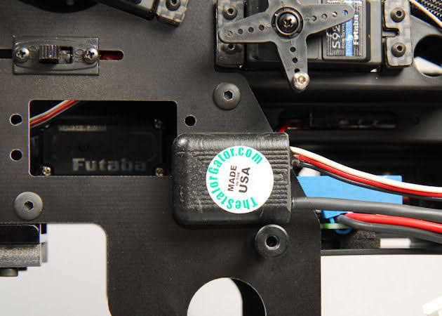
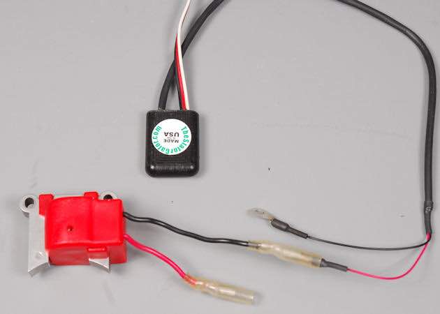
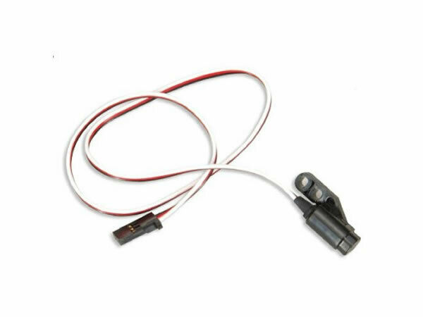
The stator gator was supposed to be used with nitro engines? I thought they (sg) were made exclusively for gassers like for zenoah as the connector is connected to the ignition black wire and the sg is installed in a different place not on the back plate of the engine. (please see pic attached).
Thankyou again for your input, I will discard the stator gator and go for the Hall effect sensor as you mentioned.
Is it possible to use a Futaba sensor instead of the align/aerospire? I have the Futaba 701 sensor with me, the others I need to order which may take a few weeks to reach me.
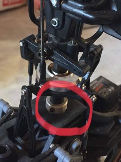
Also, Instead of installing the magnet on the gear is it ok If I install both the magnets on a plastic or delrin or an aluminum collar and install the collar on the main shaft? Below the swash (like in the pic attached) will that be ok or should I just install on the gear. The only reason I’m hesitant to install on the gear is if I have to change the gear (which I often do on a bergen heli) then I have to reinstall the magnets on the new gear again. Please advice. Also is it important to install two magnets or is it ok if I just install one magnet?
What is the ideal temperature (or safe temperature I should not exceed) measures at the head of the zenoah 260 engine? My next is to get some temperature sensors and install it on the head and see I get any reading from pixhawk.
There is three different stator gators, IIRC. But they have a noisy circuit and the only governor I’ve gotten them to work with is a Fubata GV-1.
It does not matter where you put the magnets, as long the airgap can be controlled tightly so it properly triggers the hall effect and it measures main rotor shaft speed.
That one may work if it’s a generic hall effect. I’ve never tried it. The Aerospire, Align and even generic hall effect sensors some people have bought on amazon work fine.
Maximum safe CHT is 450F on the Zenoah engines, preferably measured with a ring-type sensor on the spark plug base. Normal block operating temperature with a sensor mounted on the block by the exhaust port is 160-180F, maximum 200F for two minutes.
Thank you Chris Olson,
It’s indeed great help with your inputs. Will try all you mentioned and update.
Is it a must to put two magnets or one is enough?
Does the temperature sensor work with the pixhawk / mp? Any link to the temp sensors please?
Sorry forgot to upload pics last time. Here they are.
Thankyou Chris.
Just installed the two magnets today, epoxy is setting as we speak. Couldn’t install it on the main shaft, hence as your advice installed it on my the main gear.
The orientation of both the magnets are the attracting side on top (outer) for the sensor to sense… (does it make a difference?)
I Should be testing out the head speed tomorrow morning. Is there any changes I should make or do in the params for gov?
Using a Futaba on these machines, will get a Futaba temp sensor for these for now… but it would be great to have a temp coming on the ground station along with other parameters.
Yes, you’ll have to set those accordingly. The throttle curve has to work right first, as the current ArduPilot governor merely applies a correction to the throttle curve for density altitude. And it relies on the throttle curve being properly set in the case where the rotor speed sensing might fail in flight.
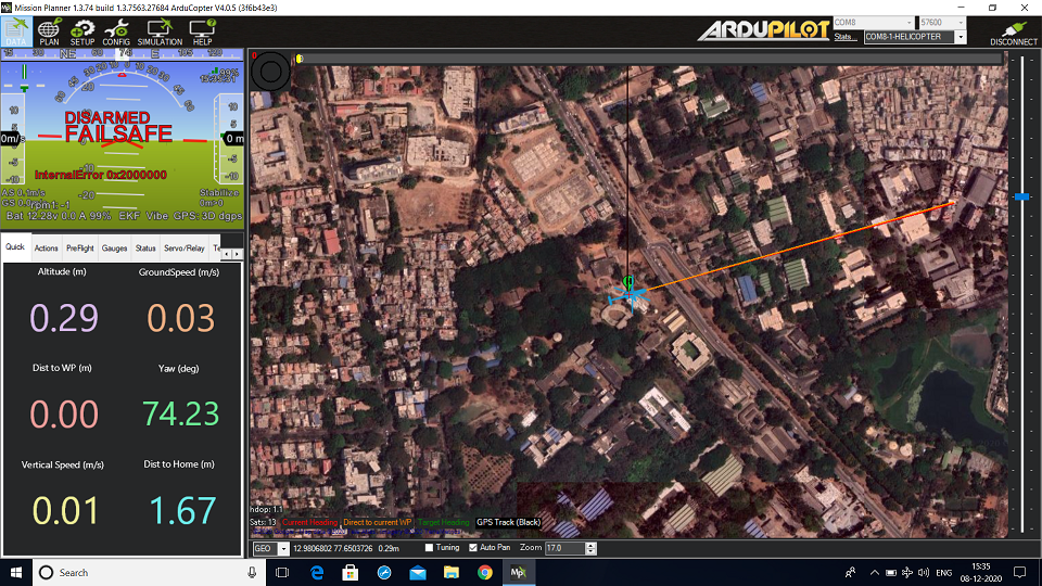
I started the heli with the futaba sensor connected to Aux5 but it was not showing any rpm, i armed the heli and started the engine, after a few seconds i got an error saying “INTERNAL ERROR 0X2000000”. and the heli disarmed itself. Please see attached screen shot of the error. This happened everytime i used the futaba sensor to aux5.
I removed the futaba sensor and put in my stator gator to aux5 and started the engine, the GCS was showing some rpm (engine rpm of around 3000 and when given power the rpm was going to around 14000 (it was run without blades) ) but i did not get the error this time and neither did the heli go to failsafe.
Connected the futaba sensor back to aux5 and started the heli, the heli after a few seconds again displayed the same error message and went into failsafe. Neither did i get any rpm display on the GCS.
I checked the sensor proximity in futaba gv1 in sensor menu and it is showing 97% so, there is adequate signals coming from the magnet and sensor.
I am still trying in mode-3 that is throttle curve not yet gone to governor mode.
What else could be the problem?
Do you have the futaba sensor wired right for power/ground/signal and not plugged in backwards? Maybe post the settings in your helicopter (param export) to see how you have the aux ports configured, might be helpful.
The sensor is the stock sensor from futaba 701 and i have not done any crimping or soldering, so should be ok i;m guessing. Checked, The ground wire’s orientation is towards the top side of the pixhawk (cube side) thats how all the servos are connected.
Still the same error. Even when on the ground and when the engine is on, when i rotate the main gear so that the magnet (in which i’m getting signal to 97% in futaba gv1) is top of the sensor, even then the error is showing up. So it is not the ignition or any harmonics from the engine or ignition, it is the sensor doing something.
I’ve herewith attached the param file for your kind perusal.
Again i tired the stator gator, i am getting the rpm displayed on the gcs and no error. But the rpm displayed is aournd 4000 in idle and when given power it goes beyond 10000 and the rpm display is going to -1, hence i increased the max rpm from 10000 to 100000.
I even enabled the governor mode and tried, but nothing. All this was done with blades off.
The main thing I wanted to see is if the relay pins are configured correctly, and it appears they are. According to Ferruccio that Futaba sensor should work so I’m at a loss to explain why it doesn’t. Your problems with the stator gator I’ve seen before, so that’s nothing new. Those things just have a really noisy circuit.
@Ferrosan any ideas why Adarsh’s Futaba sensor is doing what he describes?
Yeah, that error didn’t appear to be related. But why it happens with one sensor and not the other is confusing. Unless there is an electrical fault in the hall effect device.
Yeah, I don’t really know. That pin is configured as an interrupt for a hall effect speed sensor. So it’s a 0 or 1 signal, which trips the interrupt flag for that pin to interrupt the cpu to execute the routine. Doesn’t make sense as to why that should crash it.
@Ferrosan and @ChrisOlson
Yes it’s the same sensor you posted the pic above, came along with the 701 and it was new and unused. But the sensor when hooked to gv1 is showing 97% on one magnet.
Is there any correct way / orientation to install the magnets. What I did is I let the magnet attract each other, which ever surface stick to each other I marked those surfaces and while installing it on the main gear I installed it in such a way that the attracting surface (marked surface) is installed outer so that the sensor can sense that magnet side (I hope in clear )
When I hook the gv1, in the sensor menu, on one magnet it shows 97% and nothing on the other magnet. Is this hr correct way to install or how?
I’ll try and get the log file as I’m not going to work till Monday, let me see if I get the log file from someone.
Have ordered the aerospire and align Sensor, will replace the Futaba with them and try t once o get them…
Thankyou to both of you. Will keep you updated on the same.
 )
)