The Mauch sensor is definitely connected up with current flow in the correct direction?
this is why i’d like to know how the mauch sensors measure the voltage level.
Multimeter measures the voltage as potential difference between + and - cables.
MAuch sensors does not have a - connection, so how does it measure the voltage level?
yes of course! i’ll followed the arrows direction
The negative cable from the BEC that feeds the sensor and then onto the flight controller.
If that is creeping up above battery negative (0volts) under load, that would be the difference you are seeing.

Hi everybody,
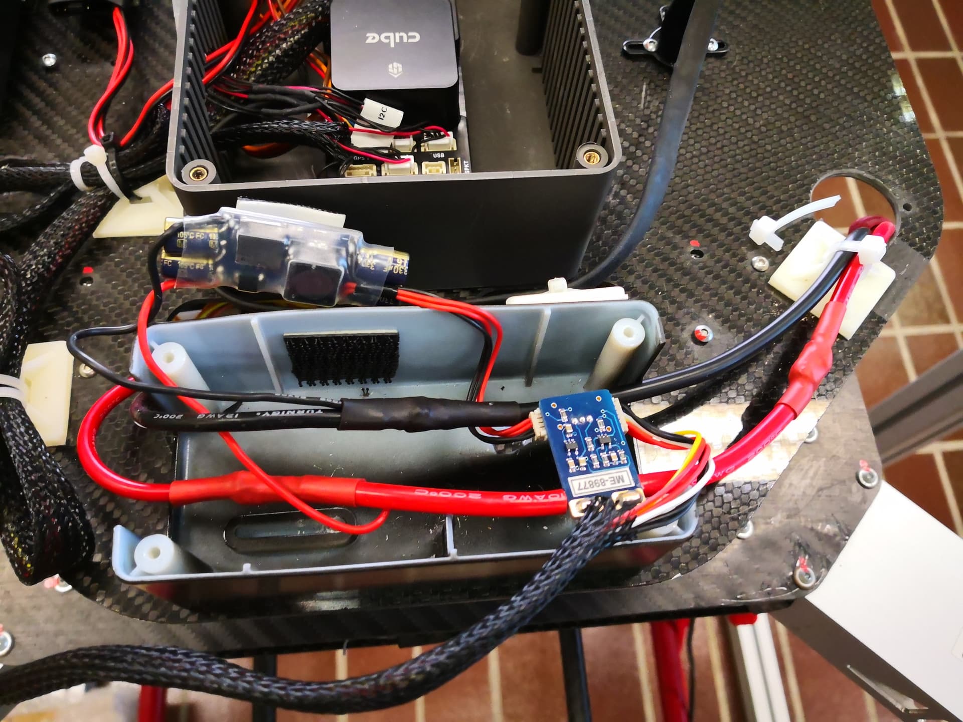
i’m done some improvements in the electrical cabling as you can see from the picture above…
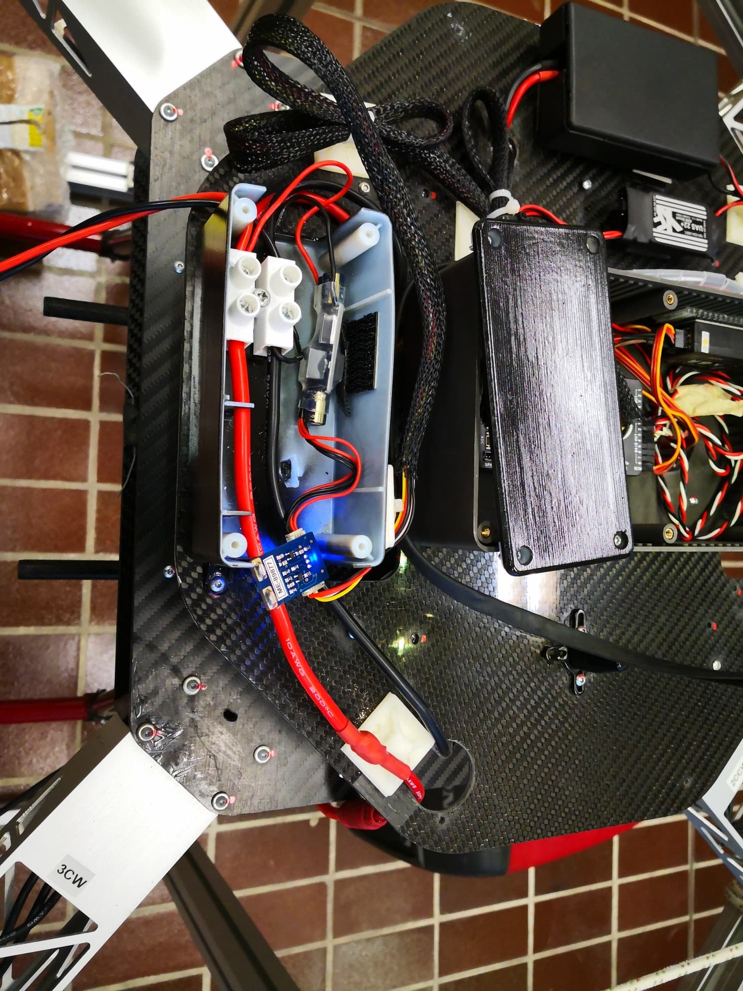
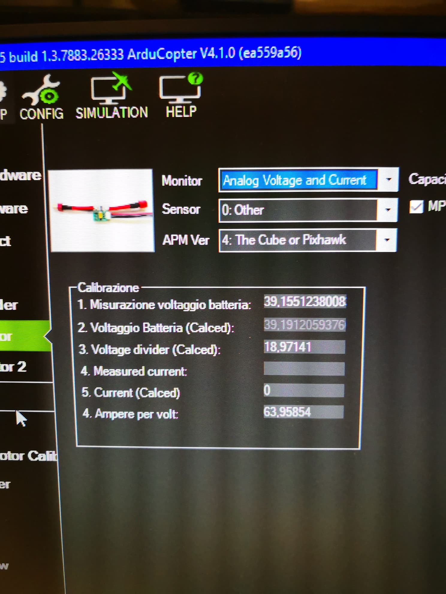
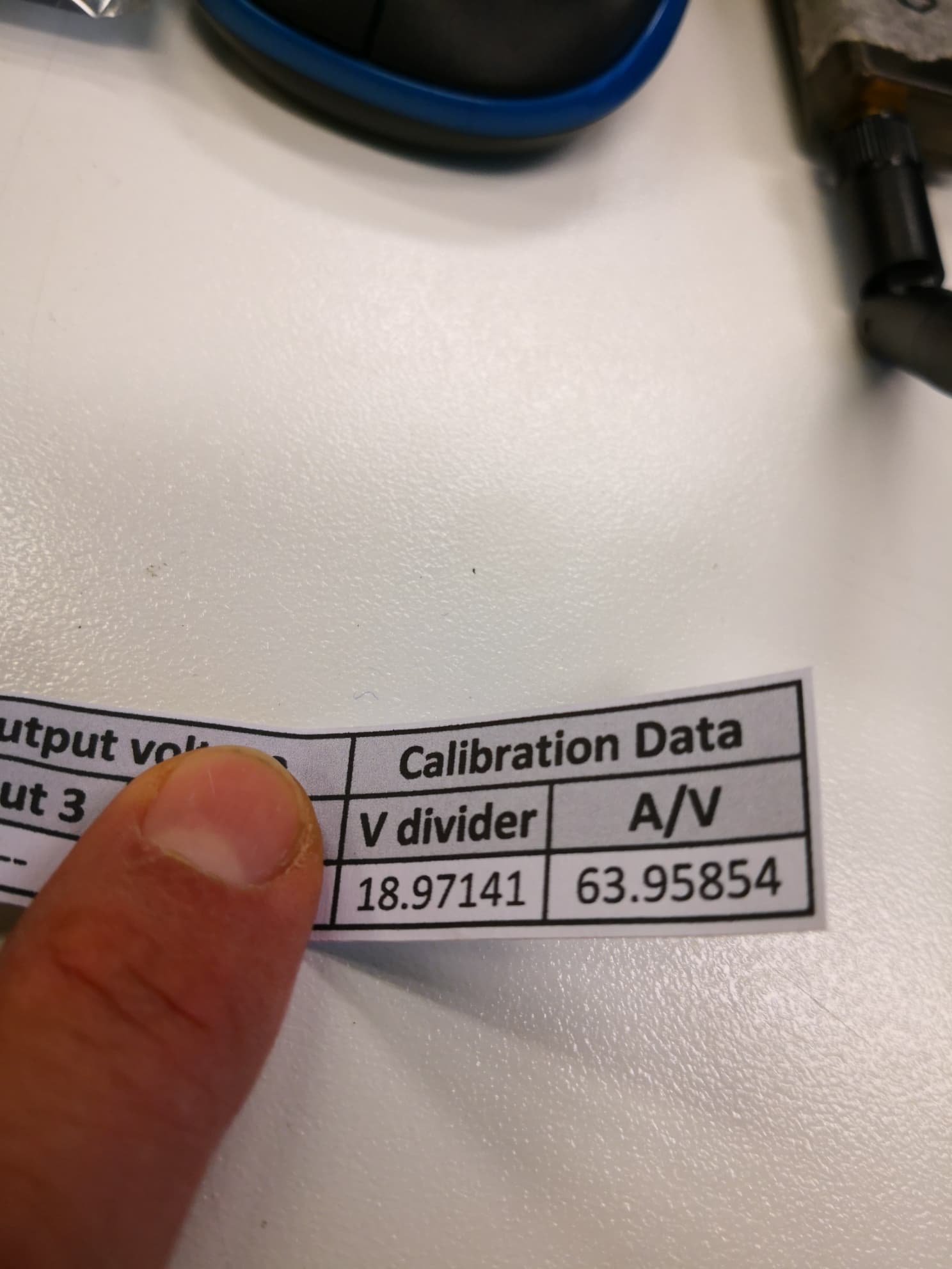
Even reinstalled a new sensor with its own Vdivider and V/A paramenters which i’ve set in mission planner battery monitor settings.
Started a new test which you can see the results in the video here downloadable
https://drive.google.com/file/d/15RkfqhbkICK-7hVcdcwGZCqacjMkHfbE/view?usp=sharing
please notice the difference beetween voltage in the multimeter and in the screen…
WHYYY??
First of all, update to at least ArduCopter 4.1.2
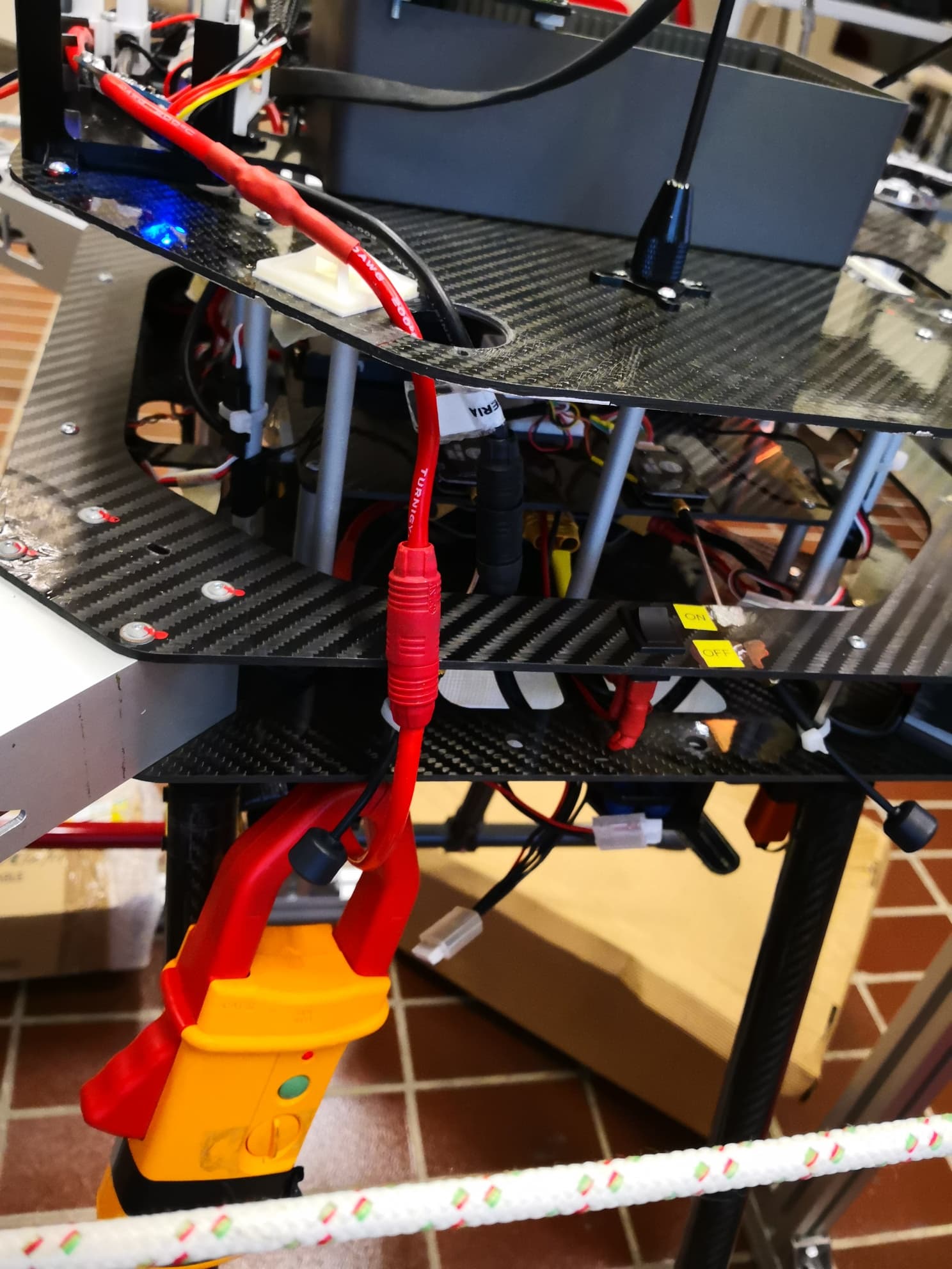
I bet 40008150 VES $ that it’s the screw terminal block and a voltage drop/difference in your negative wiring.
It looks like the BEC, who’s ground is used as a reference for the Mauch sensor, is wired in the “BAD” side of that terminal block. Those terminal blocks are really built for low current mains voltage.
With that amount of current flow, it wouldnt surprise me if the magnetic field from the wires are also affecting anything nearby, even the BEC. Layout could be important.
38 volts at up to 200 amps needs special consideration.
I did update my system to 4.1.0. it doesn’t change much
This is the reason why we need to recalibrate rather than using manufacturer’s numbers.
Hi shawn, may you please explain better what are refering to?
I’m ready to do all test you are advising…![]()
4.1.0 has known bugs that you will not have with 4.1.2
But yes the voltage readings will not change.
Recalibrating wont help in this case, even if the Mauch-supplied figures were a tiny bit off (which I doubt), because there is a voltage drop somewhere due to resistance and that will cause the measured voltage to change with current.
The voltage is measured between the BEC ground and the battery positive. The BEC ground has a resistor between it and the battery, in the form of the terminal block and non-soldered connections.
The terminal block needs to go!
If there are two batteries then use both Mauch sensors and wire it all up permanently as per the Mauch diagram I referenced earlier. Each sensor will be fed by it’s own battery (ideally). Connect the BEC at the junction of the positives and the junction of negatives.
If the battery pack is one giant pack and there isn’t two separate sets of + and - terminals, you can parallel up the Mauch sensors. Don’t stack the sensors tightly together, keep some airflow and distance between them (they are measuring a magnetic field inside after all)
Use your sensor hub.
ok thanks. next time in the lab i’ll update to 4.1.2
So you mean the white terminal block…I’ll remove it and test it again.
I though it won’t affect measurements because it’s after the sensor, and not between sensor and battery.
I have one single big battery pack. it’s a 10S with 22000 mAh. Right now i’ll try to use only one sensor, beacuse i’m pretty sure the current draw won’t excess 200A. If evertything will work, i’ll update with two sensor for a better security (in case of inaspected high current draw)
thanks for now.
I’ll keep you updated!
Have a good new year!!
Terminal block removed…
Still have the same problem.
First connection with out any current load: Mission Planner Voltage = oscilloscope Voltage
Mission planner voltage (MPV)–> it’s the voltage read by mauch sensor and visualized on mission planner
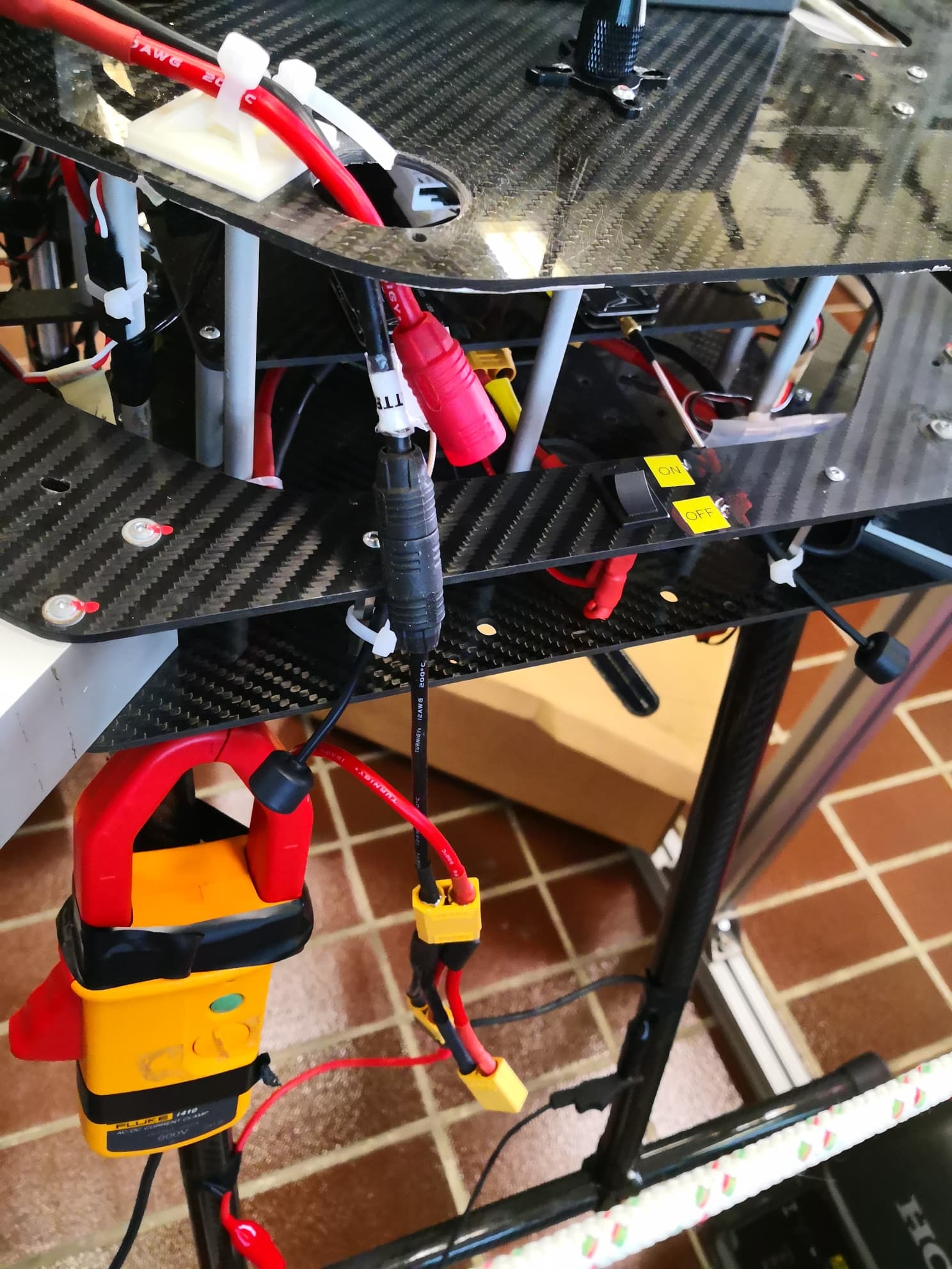
Oscilloscope Voltage (OV)–> it’s the voltage read by an oscilloscope connected on battery cables.
During Motor test (so with low current draw): MPV = OV
During motor spinnig: As much as the throttle raise, the difference between MPV and OV increase. So The higher the current draw is, the higher the voltage reading error is.
Right now i really don’t know how to achieve a coorect voltage value during flight ;-(
If you’re getting such a large voltage drop then it sounds like there is a high resistance point somewhere in the circuit.
Have you tried just feeling the wiring out for hotspots? With the amount of voltage drop on your machine I would expect there to be a bad connection somewhere between the battery and ESCs causing the drop, with the amount of drop you are seeing it would be burning hot with the amount of watts it would have to be dissipating during a flight. PDBs, power modules and connectors are common failure points. A thermal camera would be ideal but even just feeling it with your hand will let you know if its too hot.
If all that checks out then its either a sensor or sensor wiring issue.
Have you tried measuring the voltage at the ESCs to verify they are getting actual battery voltage under load?
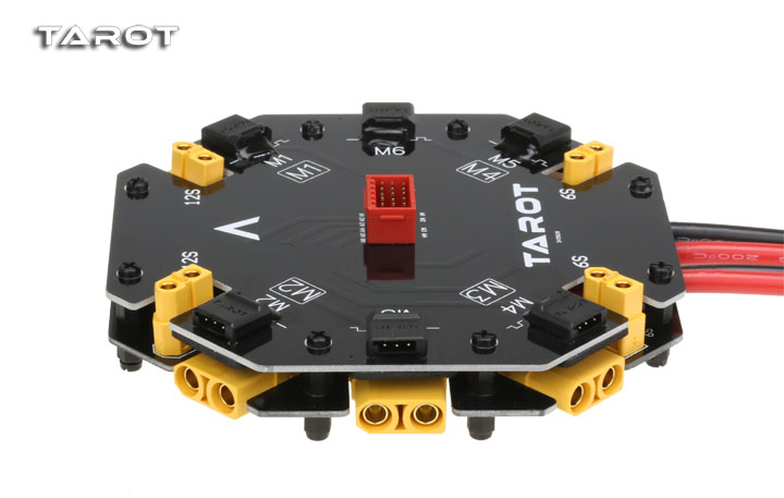
yes, i tried to measure the voltage after the board connection. Actually the voltage is lower than the real voltage measured at the battery cables. Therefore the power board is a standard Tarot power board. I assume this is built without high resistance spot…
i updated the firmware to 4.1.3 but now, in addition to voltaga issue, i have another bug which never shown before. “EK3 non started” ;-(
I tryed to recalibrate the compass but in the three green lines, the compass 1 ones does not achieve the end causing failure. I think i stayed better whit the old one.
TOmorro i’ll try to reinstall eveything from the beginning…
No, the new firmware does some tests that the old did not. Do not downgrade. Fix the issue instead.