I’d like to better control the motor’s spinnig with the throttle input.
Right now, in stabilized mode, even if throttle is set to 30%, motors start rotating faster and faster. I think it’s because drone is secured to a fixed bench and the flight controls is trying to take off over powering the motors. Indeed, even if throttle level is fixed, RC_IN output is increasing step by step until full-scale.
How can I control the motors rotation directly?
It’s all refered to the tests i’d like to carry on.
I would like to measure voltage, current draw at different throttle step (10, 20, …80, 90, 100%)
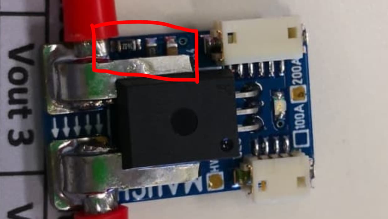
exactly. The sensor is ACS758ECB-200U-Pff-T with a sensitivity 20 mV/A.
Instead a battery, do you suggest to connect a power supply module?
do you think parameters included with sensors are incorrect?
each sensor has its own parameters. In particular this has
Vdivider 18.97141
A/V 63.95854
which are working fine during static state.
I am not sure about the Vdivider, but you can check yourself by looking at the resistors values in the circuit. About the A/V, it is inverse of V/A (which is 20mV/A for this ACS), so I guess I should be 5A/V - sorry for my previous post (it was 50V/A which is wrong)
My suggestion is to connect your drone to the power supply, without flying, check how much voltage, current it consumes and change the parameters: Vdivider and A/V to match which would be shown in the power supply display
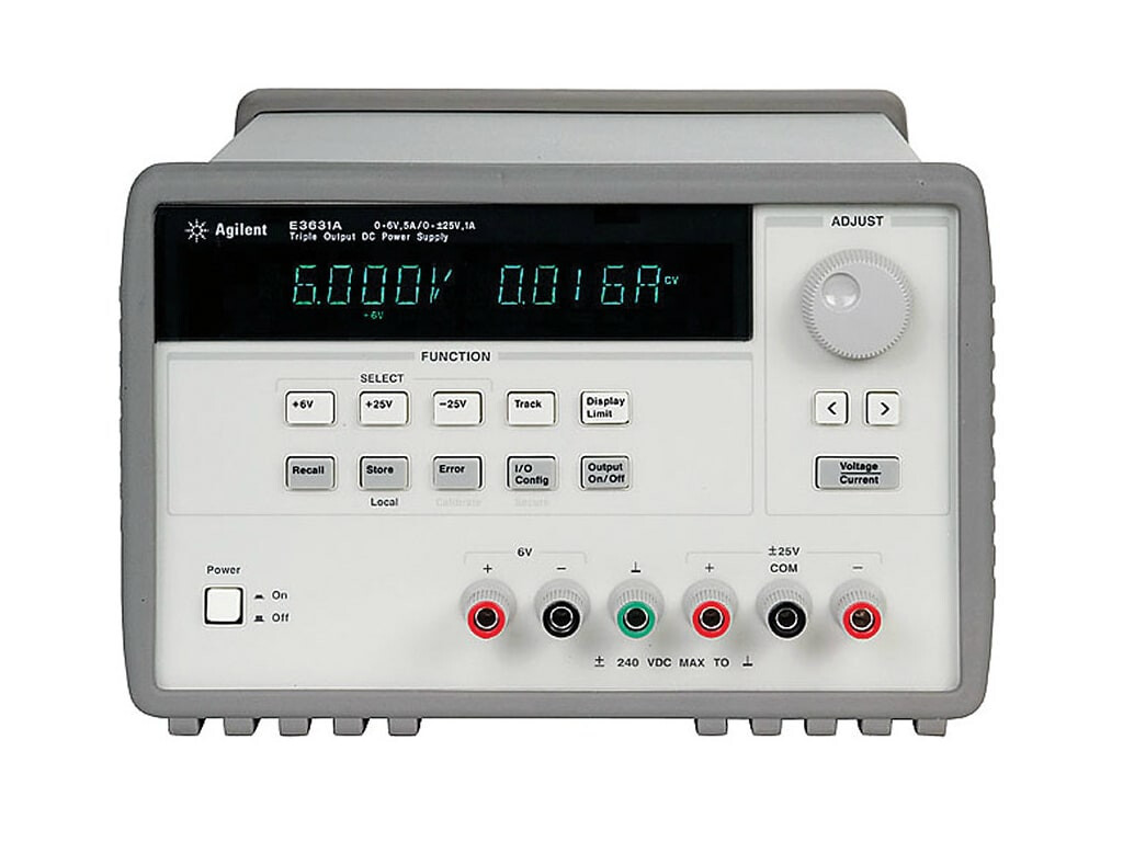
Example photo below to see how much voltage/current it takes at static state (no flying, rotating motors)
the problem is the amount of current draw.
With a power supply i can manage a low current, which here goes up to 150 Ampere at full scale.
I think i can try with 3 car battery connected in series. i can reach 36 volt with a high capacity.
Voltage will be measured with a multimeter and current with the clamp. In this way the voltage will be stable.
What do you think?
I did not understand how to do it, sorry
I’m using the sbus port on the receiver. All input are running from radio to pixhakw via sbus port.
In the parameter list (which i’m attaching) on servo1_function, servo2_function,…are set 33, 34,35, 36 as explained in the quadcopter set up.
C1,C2,C3,C4 out put are decided by pixhawk.
How can i bypass this control?
thanksparameter list.param (14.7 KB)
I agree, just want to share my experience when I deal with these kinds of analog measurement. I always try at low current draw first (no motors rotating) → make the Ardupilot read the right value of the current by changing BATT_ parameters → let motors rotate with out props → check the voltage, current read → increase the throttle → check the current again → replace the power supply by the battery, add the props, use clamp amperemeter, hold the drone in the ground → increase the throttle → compare the amperemeter with current read in Ardupilot → adjust the BATT_ parameters of needed.
Assuming you have the quad
In Mission Planner → Top bar, CONFIG → Full parameter list
Find and change:
SERVO1_FUNCTION to 53
SERVO2_FUNCTION to 53
SERVO3_FUNCTION to 53
SERVO4_FUNCTION to 53
Press Write params in the right
This is what it means: Complete Parameter List — Copter documentation - your radio channel 3
Now when you increase the channel 3, these 4 SERVOs changes. Remember to remove the props before doing this
Tests are proceding. I did everything sudgested but it’s not working.
I removed the props and proceded with low current draw setting tests.
I’ve set the parameters (V divider and A/V) to let match values between mission planner and multimeter.
After that i reinstalled the props and tried step by step if data were match.
I tried at different throttle level…30, 40 , 50 60, % but there’s no matching. The more throttle is raising, the more the gap increase. At 50% throlle i’m reading 37.5 volt in mission planner while there’s 38.5 volt shown in the multimeter.
After that I tried to calibrate the sensor parameters with props mounted.
So I started with 30% throttle and set the V divider and A/V to let match values from mission planner with multimeters ones.
The more throttle were raising, the more the gap were increasing. it’s not working.
So I tried to calibrate the sensor (Vdivider and A/V) at 45% Throttle.
With this setting I have a high voltage value shown in mission planner at the beginning, matching the correct value at middle throttle range, and a low voltage value at high throttle set.
In conclusion is impossible to find a right Vdiveder and A/V parameters which are working well during all flight time.
I’m starting to think that this sensor suck!
Can you sudgest another model/way to measure the battery voltage?
thankssss
So sorry to hear that!
I do not have the Mauch sensor here to conduct the test with you. By looking at it in the internet, I guess it uses voltage divider and ACS for monitoring which is the same to the circuit I made myself.
From designing phase, I did calculating before putting the value of resistor, so I knew voltage dividing factor in advance. For the ACS, the A/V is given in its datasheet, I just need to tweak the offset for very small amount of number.
Actually, I kept the A/V constant and tweaking BATT_AMP_OFFSET
BATT_VOLT_MULT should be easier to find.
You definitely cant expect valid results using that screw terminal block. At these currents and voltages you need high quality soldering at minimum. Milliohms will matter a lot!
You will have to trust the manufacturer, since Mauch have been doing this for a while now, and settle on a permanent design and layout, build it and then test it.
Thousands of multirotors of all sizes are using these Mauch sensors.
I would not mess around with changing the motor outputs to RC passthrough - you have large motors and props and it could be extremely dangerous. Only use the MissionPlanner motor test.
i’ll try to clean up all the circuit, removing any unused components…and test it again.
Eventhough my problem is the difference between voltage measured by multimeter and mauch sensor.
I’m connecting the multimeter connector after the mauch sensor. The raw electrical cables connection should affect both values, multimeter and mauch ones. Am i wrong?
During tests the drone is closed in a room with a polycarbonate windows so i can control the behaviour from a room next door. I’ll never do such a test next to it.
The offset is needed to adjust. Keep the BATT_AMP_PERVLT the same and adjust the BATT_AMP_OFFSET to keep the current read by Mission Planner close to the current measure by multimeters.
I do not have the sensor to test with you but @xfacta may get the point.
If you can read the code printed in the body of the resistor and figure out the value of them, you can verify the “V divider” in the note you received from the manufacture.
is there an electrical scheme of this mauch sensor HV 200A 4-14S.
I was not able to find it anywhere.
I have understood how it measure the current draw (with the ACS758 Hall sensor), but i did not figured out how it assume the voltage level.
Perhaps does it measure the voltage drop along a fixed resistor?
I don’t think the schematic is available online. It takes 14S as a maximum voltage (~60V) → divided it by a factor that output is within the 5V or 3.3v. For this circuit, I think the division factor should be >= 12 (60V/5V = 12). As long as the input is <= 14S, the system is still be fine.
Above, it is noted in the paper that the divider is 18.97 but I am skeptical so I suggested you should figure out yourself by looking for the resistors value.
The voltage and current sense wires into the flight controller have a maximum of 3.3 volts. So 60/3.3 = 18.18 for the voltage divider. Allowing for variations of resistors then the Mauch-supplied numbers are correct (of course).
You don’t even need to check the resistors yourself, just connect everything up and do the voltage calibration via MissionPlanner → measure the real battery voltage, type that in, voltage multiplier is calculated and set.
it’s what i’ve done at the second attempt. Actually I did it at different throttle range because I was wondering that without load the calibration could not be well executed.
The problem is that still trying different settings, I have an initial match between voltage read by the multimeter and voltage shown in mission planner.
Than increasing throttle, I notice an even greater deviation between mutimeter and mission planner values.
While in mission planner I have a rapid decrease of voltage value, in the multimeter I notice a lighter decrease in the voltage behavoiur. This is not due to the battery integrity.
It may be due to the raw electrical connections i did.
Tomorrow i’ll be in lab. I’m going to clean as much as possibile the cable connection, and retry with more tests…I hope i’ll solve this mistery ;.-)