Goodmorning every body,
I need some advices. I did several tests and i’d like to find a nice solution to fix the problem.
My equipment is a quad copter with 4 KDE motors (KDE6213XF-185)
i’m using a Pixhawk black cube 2.1 with a current sensor Mauch HV 200A 4-14S
AS battery i have a 10S with 22000 mAh
Running mission planner with arducopter 3.6.9
As explained on arducopter online guide, i have installed, calibrated and set the mauch parameters on battery monitor setup. It results in a perfect match between real battery voltage (measured with a tester(multimeter)) and the shown voltage in mission planner (measured with mauch sensor)
The deviation starts once I begin flying. After 30 seconds of full throttle, i notice a BAD BATTERY error with a shown voltage of 26 Volt, while with the multimeter i know that the battery voltage is still at 35,5 volt.
Same problem with ampere calcutation. I notice in the log file a 200A absorbtion at full scale, while with a multimeter i measure 158 Ampere.
This is a pure test carried on in a laboratory field. In a real situation i’m not using a 100% throttle for that long time.
But during a real mission, i have big issue with time regulation.
I set battery allarm at 33 Volt. Normally after 3 minutes mission i’m forced to land due to low battery allarm while i’m sure the real battery voltage is not so low.
Please find here attached Log file with related video about multimeter values.
any sudgestion are really appreciated. Even a new model of voltage module i may mount on my quadcopter.
thanks…
I know release 3.6.9 is a oldone, but with it i’m having great results flying my quadcopter.
It’s a big drone equipped with very expensive playload. I’m really afraid to update the software incurring in undesidered errors during flying,
It takes me months to optimaze the drone and all software parameters.
Initiallly i had big issue with magnetic interference, pids set up, and so on.
Now it’s flying very well.
All tests have been done with a light playload with an average flight time of 15 minutes.
Last test were done with a 6 kg payload resulting in a drone total wiegth of 22 kgs.
Flight time noticeably decrease to 3 minutes.
With these voltage tests i found out Muach is not working properly during high current absorbtion situation.
I think arducopter release doesn’t influence voltage measurement.
A Mauch sensor is fine, you wont need anything else.
Disable BATT2_MONITOR,0 since it’s not used and not configured for anything anyway.
According to logging the battery voltage is going very low very quickly, so either the battery is bad or the Mauch-related settings are not put in correctly.
What values came with the Mauch sensor?
Do you have a good quality BEC to supply the Mauch sensor (and then supply the flight controller) ?
Wiring - is the Mauch sensor the only thing in series between the battery and the ESC’s ?
Also definitely set all these:
ARMING_VOLT_MIN,36.90
BATT_CRT_VOLT,35.00
BATT_LOW_VOLT,36.00
BATT_FS_CRT_ACT,1
BATT_FS_LOW_ACT,2
MOT_BAT_VOLT_MAX,42.00
MOT_BAT_VOLT_MIN,33.00
Now when it wont arm, or does battery failsafe before you expect DO NOT change any of the above values to try and make things work. That only causes more problems. You need to fix the voltage and current sensor calibration, or get a new battery.
Next step is to upgrade to at least 3.6.12 since there are very important fixes. Then probably upgrade to latest stable. Any parameters that are different get converted.
Hi Shawn, thank you for your reply.
Let me ask one to one to your questions.
Disable BATT2_MONITOR,0 → i’ll do it and see if anything changes
Battery voltage is dropping very quickly because there’s a huge current absorbtion. The value is raising from 5 Amp to 160 Amp in few seconds. But my problem is not focussed in this changing, on the contrary is focussed in the deviation beetween real voltage drop and mauch acquired voltage drop.
After 20 seconds, while the mauch sensor is reading 28 volt, the real battery voltage is up to 35 volt. This different between “mauch” and real value is not acceptable.
As explained before I’m doing these tests on a lab structure, so i can connect a multimeter directly to the battery cables to figure out the real voltage behaviour.
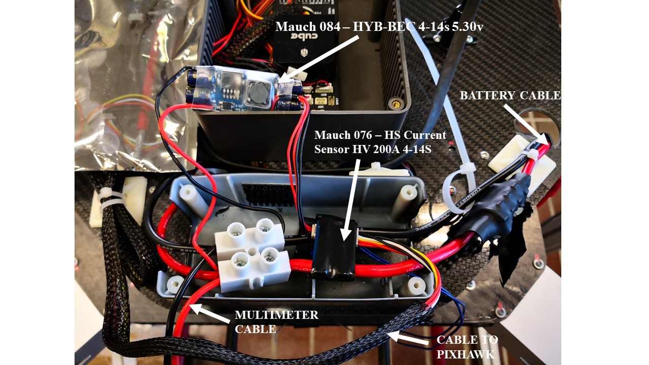
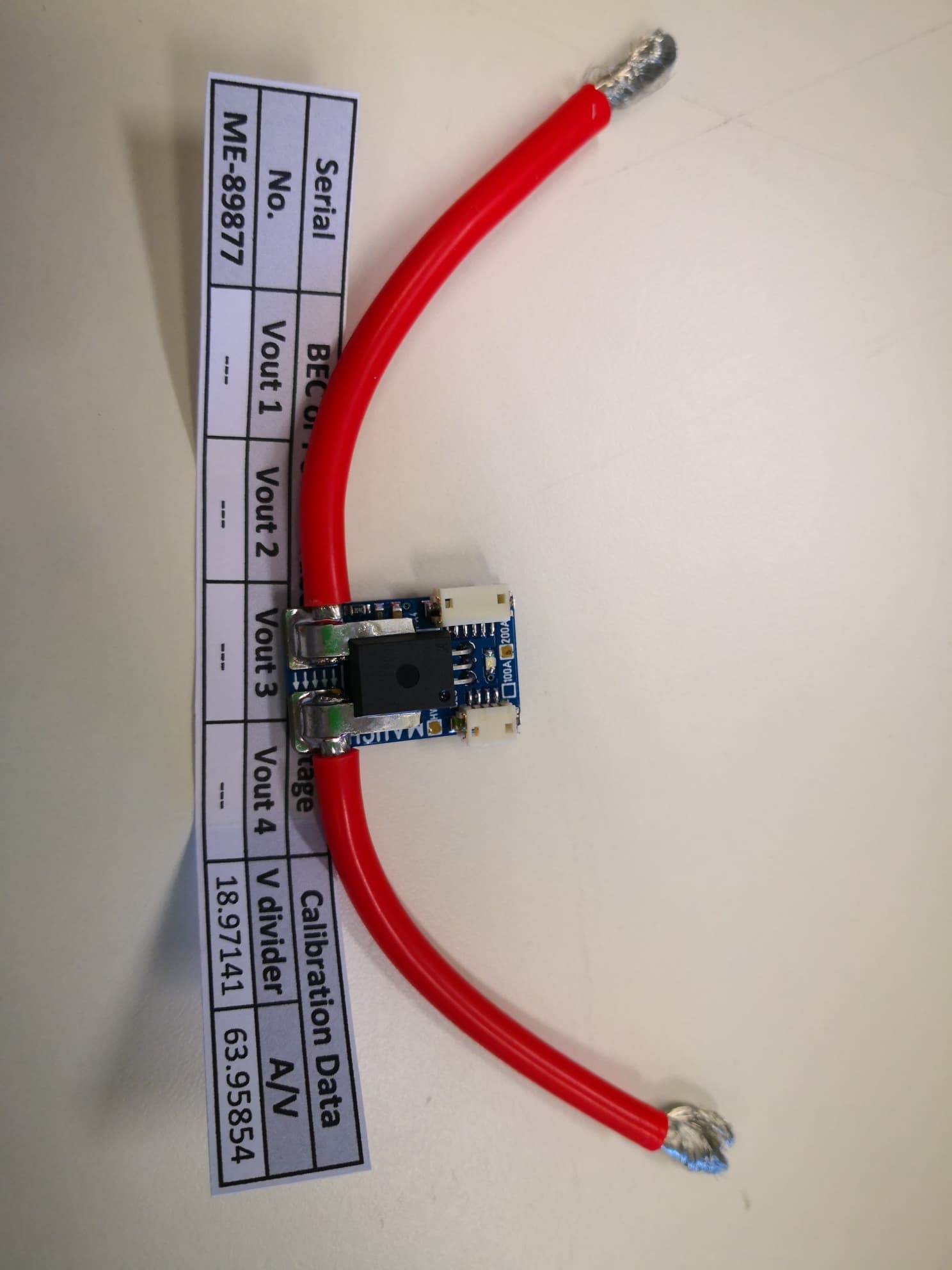
I’m using a Mauch sensor HV 200A 4-14S coupled wiht his BEC Mauch 084 – HYB-BEC 4-14s 5.30v.
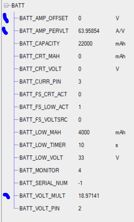
This sensor cames with its own calibratign parameters as voltage divider and Amperes per volt. This values are working fine at the beginning. I followed everysingle instruction as explained in mission planner “monitor configuration” calibration.
The mauch sensor is connected direcly on battery cables. There in nothing beetween them.
Furthermore I measured the Bec current which supply the power to the mauch sensor. It’s stable throughout the test duration.
I have set the min battery voltage to 33 Volt when landing falesafe mode take place.
I’m not wondering about battery integrity. This can cause a less time fly.
I’m wondering about the situation that i’m flying, mission planner is telling me that the battery current is about to 34 volts while in real is not! I could flight more because the real battery voltage it could be at 36 o more. I’m losing a big part of my battery capacity.
I hope i have well explained my problem and tests i’m carring on.
Thanks to anyone may help.
Yes I follow you, thanks for clarifying.
If you are seeing that reported voltage drop then either
a) the sensor is faulty and suffering some heat related problem
b) there is a resistance problem with wires or connectors between the sensor and battery
If you fly so there’s plenty of current draw and heat build-up, then land , would the voltage reading be correct at low current draw ? What about medium current draw, like when armed but not flying?
a)I tryed changing sensor…(i have three of them)…the problem still remain.
b) I’m using a AWG 10 cable for connection. Distance between battery and sensor is about 20 cm.
Further more i connect the multimeter directly in the sensors cable, so to avoid any cable dispersion.
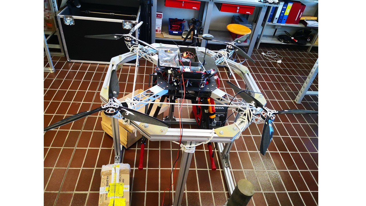
next week i’ll post a photo of my drone in the lab. Right now i’m out of office.
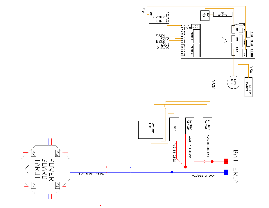
Here’s the electrical scheme of my drone.
As you can notice it were used two sensors mounted in parallel cause we were afraid to exceed the 200A limit.
Now I’m proceeding my test with only one sensors. The problems are still the same.
When armed there is a 6 ampere current draw. The voltage level is fine.
The more the current draw incresaes, the more the deviation between real and measured current take place.
In the first message you can download the video where multimeter and amperometer are recorded.
I have no idea right now, except that the sensors works badly at high current draw.
I have to find a way to have the real voltage level during flight.
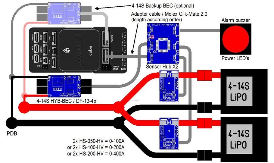
I suspect the sensor hub is set up to use the two voltage/current sensors in parallel when each has it’s own battery pack as per the diagram from Mauch
And you have to average the voltage divider and sum the amps-per-volt values:
Voltage divider = (Voltage divider sensor 1 + Voltage divider sensor 2) / 2
Amp/ Volt = Amp/V Sensor 1 + Amp/V Sensor 2
If you have only one big battery pack then you would only use one sensor. What do you expect the maximum current to be? These sensors can handle some over-current for a short time.
At the beginning we aspected e current draw higher than 200A, this is why we set a double sensor with its own hub to avoid over current.
After several tests, I measured a maximum current draw of about 160 Amp, so this is why I set an easy system, with only one sensor without any hub, even more because I have a single big battery pac (10s with 22000 mah).
Sensor maximum current is 200A. In any case I’ll pass this limit.
Might I suggest a small step backwards. Check that each sensor works individually (not parallelized). Get that working and of course keep it under 200A. Get the voltage, voltage output from the sensor, and current at a few points in your current range. That will give you the coefficients for that sensor.
Then parallel them. And get the same data. And find where your voltage drop is occurring.
I wonder if the voltage dividers in the two sensors you have parallelized are interacting to give a different ratio then designed. If you removed the dividers I have a guess this might go away. Basically, the voltage sensing AKA the 2 pairs of resistors are in parallel as well…
Basically, you want two current measurements, but only need 1 voltage measurement because voltage is the same where they parallelize (ideally). Note at high currents thinking about the resistance of wire, connectors, and board trace size matters.)
Hi josh,
i knew that the photo i posted may dislead a bit, but as i explained previosly this was the first setting (which by the way i did not, because I join the project later)
As you sedgested, I did exactly the same process. I was afraid that two sensors were not working well together, so firstly I made sure the current draw was under 200A, secondly I removed one sensors and the Hub.
Right now the system is working with only one sensors.
All my tests are related to a single sensors set up. Tomorrow i’ll be in the lab. I’ll post a photo.
What i’m going to do right now is to acquire severals values at different load.
for example:
voltage measured by the sensor
voltage measured by multimeter
current draw measured by amperometer
these three values acquired at differents current draw (10, 30, 50, 70, 90, 110, 130, 150 Ampere)
When analysing your video, there is something I can point out:
At static state, actual voltage: 41.6V, actual current (@ 0.4 mV) approximately 0.4mV / 20mV/A = 0.02A. In the log, I saw that the voltage was read @ 41.16V and current was 0.1A
I thought there are some parameters here we can tune for getting the right value.
BATT_AMP_PERVLT can be set to 50
Try to keep you motors rotate and check the voltmeter at 40, 39, 38… so you can tune BATT_VOLT_MULT.
I highly recommend using power supply module so you can see the voltage and current draw directly. It is easier for tunning this analog measurement. In my cases, I always take 2 decimal precision.
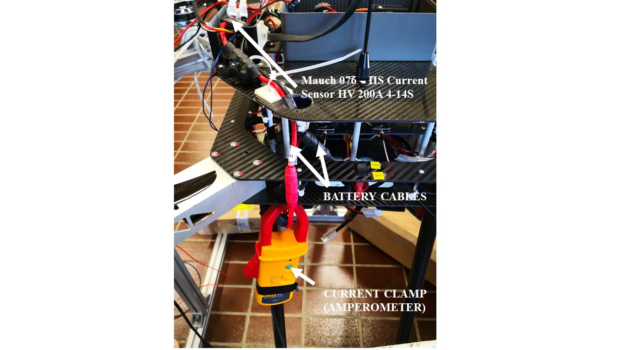
I have a lab where is possible to execute tests in total safety.
I built a test bench in a way to secure my drone during load tests.
As shown in the attached photos i’m acquiring voltage and current draw directly from battery cables with a mutimeter and a current clamp.
Mauch sensors is pretty close to the battery and BEC power supply is directly connected to the sensors.
Tests took place in the following mode:
1- battery connection followed by arming procedure.
2- stabilized flight mode
3- throttle raise from 0 to 100 % looking to voltage and current behavoiur
As you can see from my videos, the current values acquired from mutimeter and mauch sensors are pretty different.