You missed out the worst offender by far - VTX and analog camera cable runs
2 Likes
What’s a good way to trace back GPS interference? One of those usb SDR radios and run some scans at different places on the frame? There’s no way to visualize it right (ie how FLIR cameras can visualize heat)?
Ah yes VTX…best add that to the list lol.
I imagine there is a way with an RF sensor of some sort.
In my case I just knew from experience what are the big hitters and took them into account. I didn’t think of the VTX as Andy pointed out, but I don’t have one on the machine so didn’t consider it.
I have learned over the years that anything with more complex electronics on board, ESC VTX receivers…things like that. They generate RFI and nearness to the GPS can be a problem.
My drone that caused this conversation had a 15 minute capture time with the receiver unshielded and a 1 minute with it shielded. Makes a huge different. I typically shield everything I can.
1 Like
What do you use as a shield material Ricky,I may try some of that “madness” on my receiver sounds like a good solution
Hey Marty. Hope your well.
I used two things on this receiver but typically I use copper foil and then solder a wire to it and solder that wire to ground. That generally cleans stuff up for me.
In fact I do this for my compass, receiver and GPS.
So on the compass I have a 3d printed mount that has a large top thats all copper foil tied to ground.
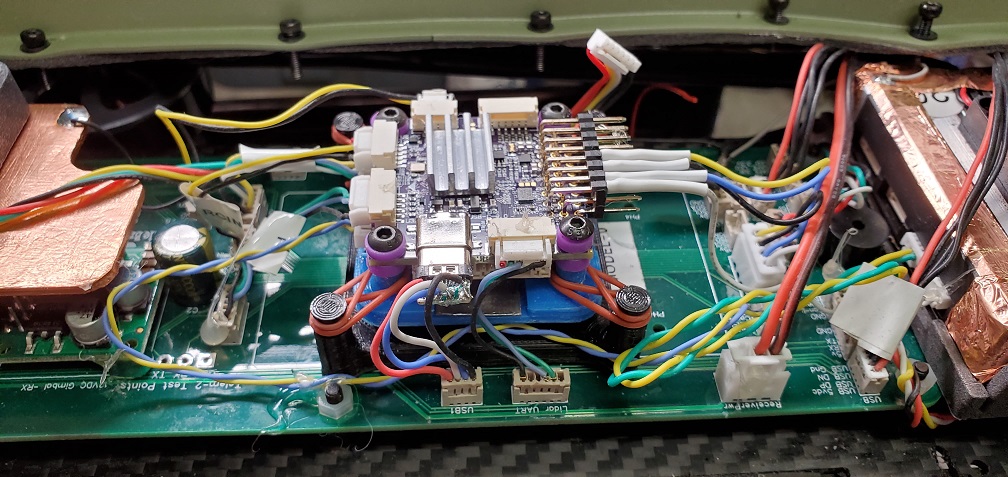
The receiver is covered in Foil and again tied to ground.
My GPS has a plastic plate under it with copper foil tied to ground.
All these things are to reduce RFI. Just stupid me I forgot to do it on the RX when I installed it.
1 Like
Thanks Ricky for that,I hope you and Susan are well and i love the wild life around your new location ,im well lost my meeka 16 yrs old as was a bit hard but over it now and had health issues but seem o/k now and loving all things ardupilot again take care my friend
So I got to fly the bird again today.
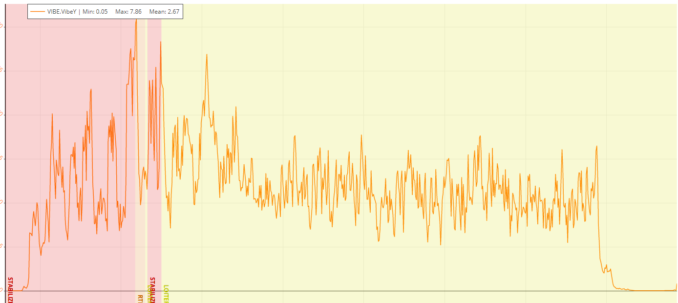
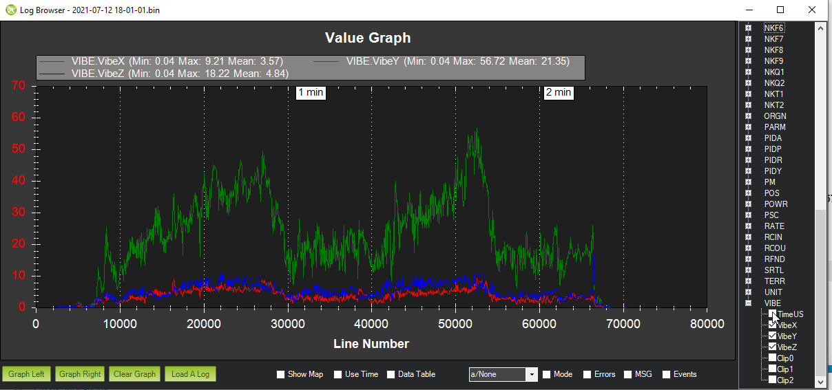
I was really hoping that the USB cable was touching the canopy and that was the cause of the Y axis high vibrations. The machine flew just fine and there is no clipping but still the Y Axis is up there.
I might try making the change to the mount with some lead attached to see if it needs some mass to dampen it.
I think there is also a fault with the Online UAV Log Viewer. When I use log UAV viewer. I see the max is around 8 on the Y axis yet yo can see in the graph that it clearly went to greater then 30.
1 Like
Mike when you say tension is different. Do you mean less tension or more.
That said these are on corners so I don’t have more or less for the Y axis. But I am wondering if I should either double up the O-ring or add the mass…maybe both
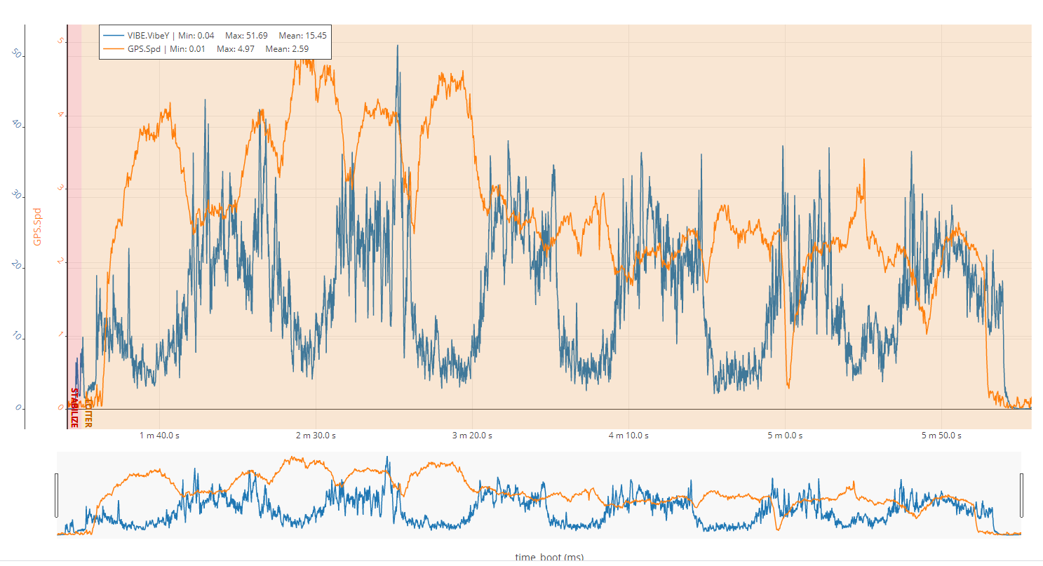
Also is this graph saying that when it goes faster it’s smoother. In some ways that sort of makes sense.
My recommendation is to do both, on all but the small Pixracer I use 2 O rings and adding the mass is part of the whole vibration tuning setup.
Your FC has an X Y and Z directions so the Y is being vibrated more as your test indicate.
So if you apply a small force to your FC in the X and Y directions does it move the same distance?
Is there anything in the frame that is likely to move in the Y direction?
So the arms move and lock into position, folding for transport. I can see there is some movement at the tip of the arm in what you could consider a Y Axis direction. I have a theory on how to test for it. I am going to check tomorrow if I can do to the machine what I want to do to test it. If I can then I will get to the field and try again.
IF its tip movement I think I can temporarily lock them out and then fly it. If the log shows the vibrations are reduced then I will free each arm one at a time and test fly. I am interested in knowing if it’s all the arms or just one.
IF this does make a difference I will then make a mod to improve on that function. If there is no change then I am not sure.
Mike I assume for the pixracers you currently use one o ring per corner and no mass. Is that correct also are you tying the o ring to a pillar that is at 45 degrees to the hole on the FC like in this rendering

My copter was folding to begin with but I found that feature to add flex and so fixed the arms in place. Though I found that to help with better autotune results rather than reduced vibrations. For vibrations, IMO its always best to find the source rather than dampen or filter in software. Non stiff arms can make a vibration problem worse and cause all sorts of other problems but I don’t think its usually the upstream source of the vibrations.
Maybe try mounting a camera like the Mobius actioncam on your MR? I found vibrations showed up big time in the video and you could see sometimes what was causing it (wires vibrating etc)
Hi Derek.
I can’t move away from folding as the drone is to large…so I need to hunt down the source. Like you I agree, find the source and establish a plan to remediate the cause of the vibration. From there Dampening will help with the rest as for your suggestion of a camera, that’s a great idea. I image I could easily mount a small run cam I have and point it at an arm. See if that’s the cause.
Great idea.
thanks
I have no Pixracers as I sold the ZMR250’s they were in, but I have added some detail to the bottom of the page I created
1 Like
Interesting
Looking at the photos I get the impression your O-Rings are looser then mine. The ones I am using appear to be much tighter.
Your X and Z vibes were low, if you can’t find something else affecting Y axis then maybe reprint the mount with the O ring posts offset to either Y axis or X axis a little more. So they are not at exactly 45 degrees from the corners of the FC. Just an idea
Hey Shawn
Yup already considered that. I have created an updated design to do just that.
It’s just so weird to suddenly drop the X and Z so drastically yet Y is up. Anyway I have another mount ready and an experiment to try this sunday assuming the weather is good.
I want to find the cause of the vibes. That said I suppose it’s possible that the mount is enhancing the Y axis in some way.
Things to ponder. Apart from that the machine flies well. Even the Yaw is dialed in much better now.
Well after waiting a week or so for an opening in the rain.
I got to the field today and tried a simple experiment. I flew ne loop on the field normally and then a second loop with the arms locked so they can’t move at all.
Here is the loop with the arms not locked.
Here is with the arms restricted.
In summary
Arms restricted.
X Axis Max 9.21 Mean 3.57 Good
Y Axis Max 56.72 Mean 21.36 Bad
Z Axis Max 18.22 Mean 4.84 Good
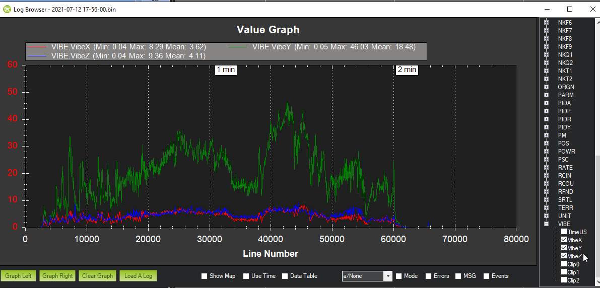
Unrestricted
X Axis Max 8.29 Mean 3.62 Good
Y Axis Max 46.03 Mean 18.48 Bad
Z Axis Max 9.36 Mean 4.11 Good
No clipping in both cases.
Its pretty clear that the restriction of the arms made it worse on all axis. But not by allot. So it doesn’t appear to be the arms moving that’s causing the Y Axis vibration.
I have two courses of action next.
1 Unplug the gimbal and see if its shaking the craft in some way.
2 Change the FC dampener to one with Mass.
After that I have no clue. But I am up for the experiment.
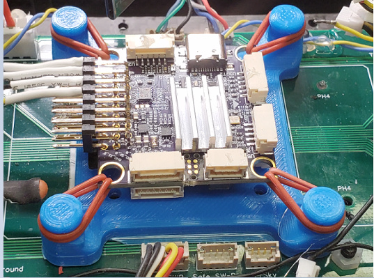
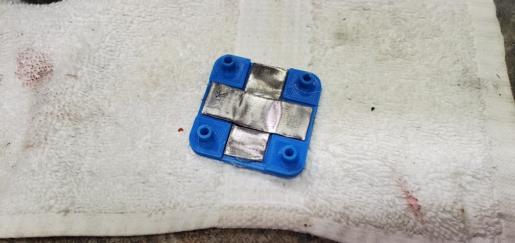
Ok this morning I upgraded the FC dampener per the input from @mboland.
The base is mounted with foam tape.
Then O-Rings to a plastic mount with lead mounted on it for mass.
Then the FC is mounted to that mount with the vibration dampeners that come with the FC.
I will give this a try next.
Got to the field today.
This time with the new dampener with the mass attached.
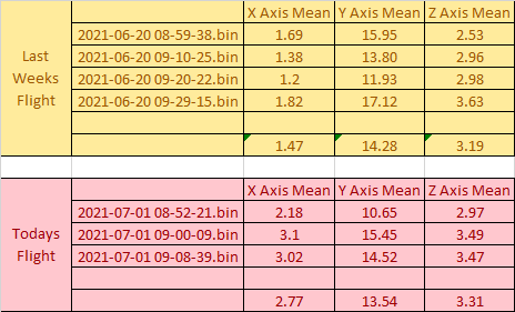
Here are the flights before the change to the dampener with the added mass.
X Axis Max 8.29 Mean 3.62 Good
Y Axis Max 46.03 Mean 18.48 Bad
Z Axis Max 9.36 Mean 4.11 Good
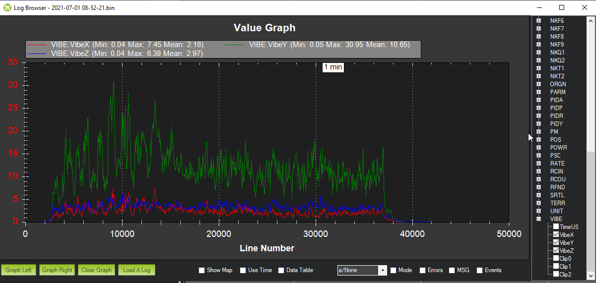
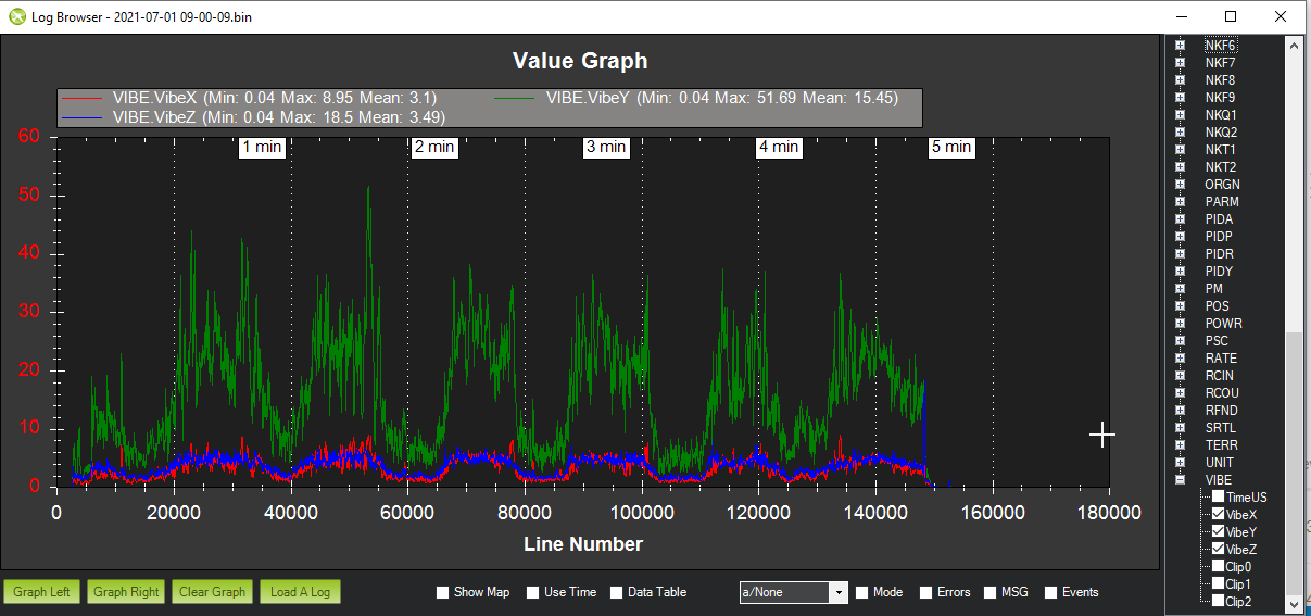
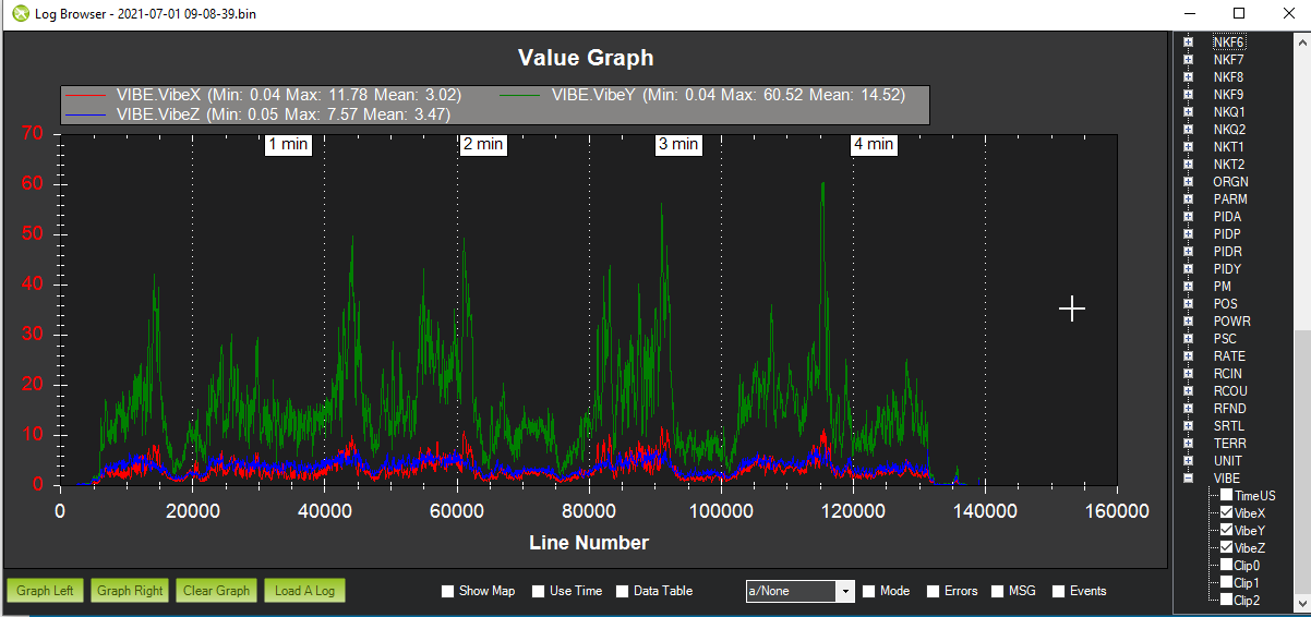
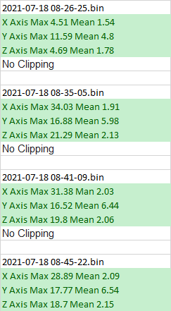
Here are all the flights from today. Some where really short…
The rest a couple minutes.
Looks like the vibes have improved a lot.
I might actually be happy now.
I would still like to see the Y axis lower, but its much better.
2 Likes