Thanks Yuri, I’ll get out my meter and check it out tomorrow. I am kind of thinking it probably means I need a new GPS board. Maybe that radio plugged into the board stressed it out. When I put it all back together. I will consider mounting the radio on a serial adapter board and powering it off of an external power source (not from the board).
Steve, That’s a bummer on the board giving trouble.
Interestingly, I had a very similar problem with an Ardusimple RTK2Bb board about 2 years ago. This is part of the email I sent to Ardusimple: "The board still seems to operate in that I can connect USB to it and see data in u-center, but the TX1 output is not working and I noticed that the 6-pin IC near it with label IBSD (or similar) is super hot. You cannot hold your finger on it. "
That may not be the same chip you have circled, but it could be the same issue just on a different port. Ardusimple support was extremely helpful. They offered to repair it, even if it was out of warranty. But I chose instead to order the part and try to repair myself rather than shipping back to Spain. Ardusimple provided the part number to me: SN74LVC1G3157DBVR. I do not know if that is the same part you need or not.
Another tidbit, Ardusimple told me this:
“The failures of this component we have seen are 2:
o Connecting it something above 6V to one of its pins,
o External short when soldering arduino headers.”
Sadly, the replaced part did not fix the board. I still have it though and it can still be used as long as I do not need the TX1 port.
The point of my story, really, is that Ardusimple has excellent customer support from what I can tell. You should reach out to them.
2 Likes
Kenny, it is interesting that you had pretty much the exact same problem. When the board quit working it did seem very much like TX1 quit communicating. It would not talk to the flight controller. Anyway, I did reach out to Ardusimple in Spain and they do want me to send the board back to them for evaluation, which I will do. I have also pulled the SimpleRTK2B board out of my base station so I can use it on the mower. I have a spare SimpleRTK2blite board that I am working on putting back in the base station. I am just mounting it on an ArduSimple mount anything adapter board to hold it and supply power. The small ArduSimple X-Bee radio module is then plugged into the header on top of the lite board. The base station is working, but as of right now it is not broadcasting any RTCM3 signal and I am still working on that. I have noticed that that little RTK2Blite board will complete a “Survey-in” on the antenna location very fast. When it had the full size board in it, it was slower.
I have put the board I took out of the base station in the mower and I have it working now, minus the RTK signal getting to the moving base board from the base station. I am sure I will get the RTK signal back when I get through going over everything.
My biggest concern is the fact that the whole GPS-Yaw system seems so sensitive and it seems to give the “Unhealthy GPS” signal often, quit working giving the huge variance from the compass reading, and flip around the GPS status from fixed to dgps. Sometimes it works fine and sometimes it is just unreliable. I am just using the original ArduSimple black “puck” antennas with the really long cables coiled up. Do I need to shorten the cables and/or get better antennas? I realize the sky conditions influence this but sometimes I am locked on to 30 satellites and it will still get flakey, and ometimes it is fine for hours.
I also intend to figure out how to get the RTCMv2 data connected to GPS1 (Rover) by using the external wire from the Uart2 on the moving base connected to the Uart2 on the rover GPS. It should be simple, “Its one wire”, but Yuri and I worked on this before until I just gave up and set GPS_DRV_Option=0. I really want to get this working now since I am setting it back up with the replacement GPS board. If I can get the signal going over the wire it might free up resources and help with the reliability problem. Maybe now with a different board in there it will work. I have also connected the 3v3_OUT pin to the IOREF pin on both GPS boards as requested by Yuri.
Below, is a picture of the RTK2BLite base station. The radio doesn’t seem to be working at present but I am working on it. I need to check my baud rates an other setup parameters. If I have that radio plugged in backwards I am sure you will net me know. I will check the pin configurations on both boards tomorrow. I used the information on orientation from the ArduSimple website, but I have learned to be skeptical.
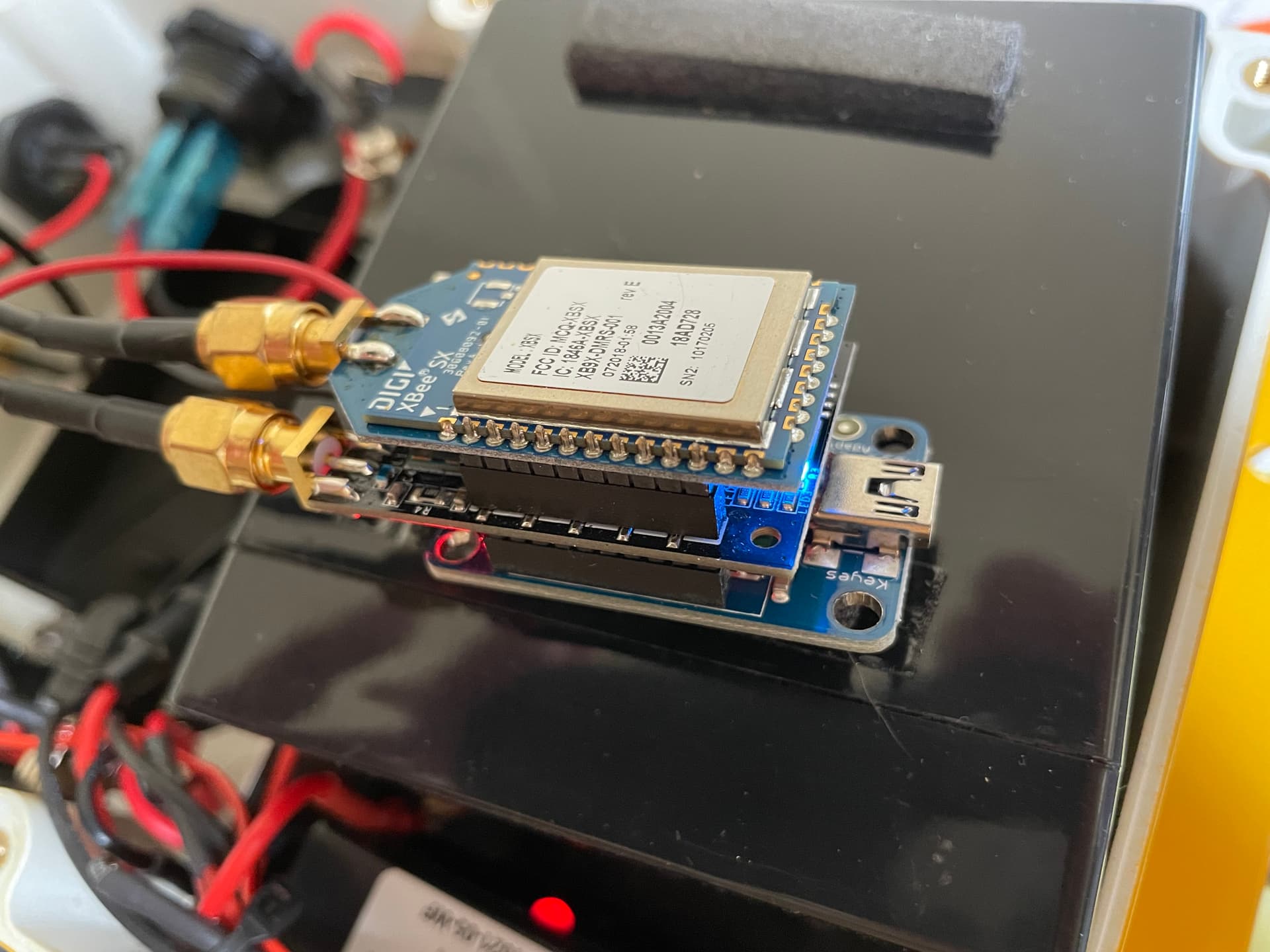
Well I am happy to report that the Simple RTK2BLite board is working fine as my base station, the radio is broadcasting the RTCM3 data to the moving base. I also went through the entire setup for the GPS_Yaw system once the new GPS board was installed and now the RTCMv2 data moves over the wire connecting UART 2 ports between the boards. I am now able to use GPS_DRV_Option=1.
Things seem more stable but I will see tomorrow as I plan to use it a lot. Hopefully, I can get some new pictures and a video soon.
Make sure you have GPS_RATE_MS and GPS_RATE_MS2 set to 200. Any faster will likely result in unstable performance. It is a common misconception that GPS update rates should be increased beyond this setting. Sensor fusion takes care of filling in the gaps quite handily.
A base station survey should typically take several hours to complete if you are looking for sub-meter accuracy.
1 Like
That’s great news that you have all the pieces working! I see Yuri’s reply below. I can’t offer anything more.
2 Likes
Yuri
I’m configuring my f9p’s for the yaw. I have one c099-f9p (just got it) and two as-rtk2b-f9p. I’m wondering if (someone has already made the mistake I’m about to make) I should/can use the c099 as the moving base to get the rtcm3 data from the built in odin wifi - from a fixed base using a similar setup to your “Wi-Fi enabled fixed base”.
maybe a better question is where is the optimal spot for the c099 : fixed base moving base or the rover?
thanks for your time
The boards are very similar in capabilities, and I don’t think it matters where you put them.
If it were mine, I’d put the two matched boards on the vehicle and use the c099 board as the fixed base.
To be clear, I DO NOT use wifi to transmit anything to the vehicle itself. I strongly prefer radios with more range for that purpose.
@Yuri_Rage @ktrussell are you guys controling your D845 servos directly from the Pixhawk or via some controller board?
I think I had mine working very early in the project before I got into all GPS setups and etc. Now it just won’t respond to the RC.
- Signal wire connected to MAIN IO _1,
- Servo is powered directly from 5v external power supply.
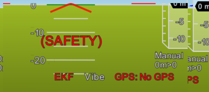
- System is Armed
- No GPS’es are physically connected
- Frame_type = ROVER
MP shows green bar moving with both GroundSteering and RCIN1, servo yet plays dead. ![]()


Although it sometimes dances randomly when signal wire is connected to PX4 eventhough PX4 is OFF! Due to some interferences?
Check your ground connections. If you don’t have a common ground between the power supplies, behavior will be unpredictable (or nil).
I see no PX4 in that picture, so your reference to PX4 hardware or firmware makes no sense.
It looks like a wiring problem. The servos are meant to be operated off of the servo rail (slots 1 & 3) on the cube. In general those servos will pull too much power from the rail if it is powered from the same power source as the cube. I plugged my servo isolator into the rail which will only take the signal and pass it to the servo through the isolator. A more current capable power source is connected to the isolator and is supplied to the servo.
In summary you need a servo rail isolator or you need to supply a higher current power source to the cube rail. I believe on the cube there is no power to the cube rail until you put some there. It is not powered through the cube. The servo rail isolators become necessary for also controlling electrical noise and voltage spikes produced by rapidly moving servos. It is good practice to protect the flight controller from all the electrical noise sources.
I disagree that specific isolator hardware is necessary. Using a separate power supply is a necessity, but there is no need to power the rail the way you describe. A common ground is a must, regardless.
Yep, sorry, had in mind Cube Orange. You mean S 7.5v Servo circuit with high currents would not cause issues to 5V Cube Orange circuit if they share the common ground?
That is correct. You must provide a ground reference for the signal line.
EDIT: That doesn’t mean ground your power supply THROUGH the autopilot. Think about the current paths and always use appropriate wire diameter.
1 Like
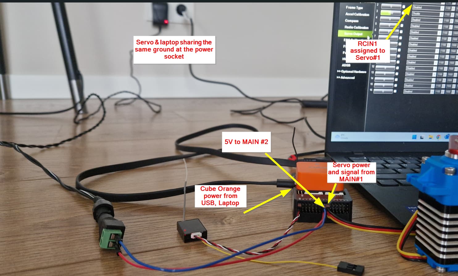
Trying to wrap my head around and remember how the hell I had it working before. It might have been on ArduPilot rather than ArduRover. But pretty sure hardware setup was:
- Cube Orange - powered through the USB (from the Laptop)
- Servo - power fed though the MAIN IO from the separate 5v DC plugged into the wall power socket.
But now this setup is not working. Isn’t MAIN OUT/AUX Ground shared with the rest of the Cube’s ground?
Or has it smth to do with these messages:

I have Force Armed it anyway
Do you guys happen to have pic of your electric hardware setup? Looked through Yuri’s amazing video’s on YT channel, but could not find it ![]()
------ EDIT, UPDATE:
Hallelujah! It took only 3 days of struggle and it is working now. And I am not even sure what exactly fixed it. Most recently I played around BRD_SAFETY_MASK and BRD_SAFETYENABLE, but now servo seems to respond to RC whatever values I set there… Armed or not… ![]()
Conculusion that it works with above setup, but:
- Regardless if the laptop is connected to the wall socket (at least without common ground there)
- Also works when CUBE is powered from the separate to servo power bank.
Question: can servo be fully powered with 7.5V and e.g.10A using external power connected to the Cube’s MAIN OUT power pins? Just as I did now, but now I am providing only 5V being concerned that it might burn CUBE, servo is not using much power now too.
In answer to your question, yes the servo can be powered off the servo rail at a different voltage than the cube. The servo rail power distribution system is not connected to the cube power system. It was built that way just for this purpose, to have higher voltages and currents. I am not sure of the max current of the rail, but I would believe it could handle 10 amps. If the ground of the servo rail power supply is connected to the ground of the cube power supply, you should be good.
1 Like
That’s still a giant pain in the ass. I will continue to recommend against the heading kit in favor of two full boards that can be auto configured.
3 Likes
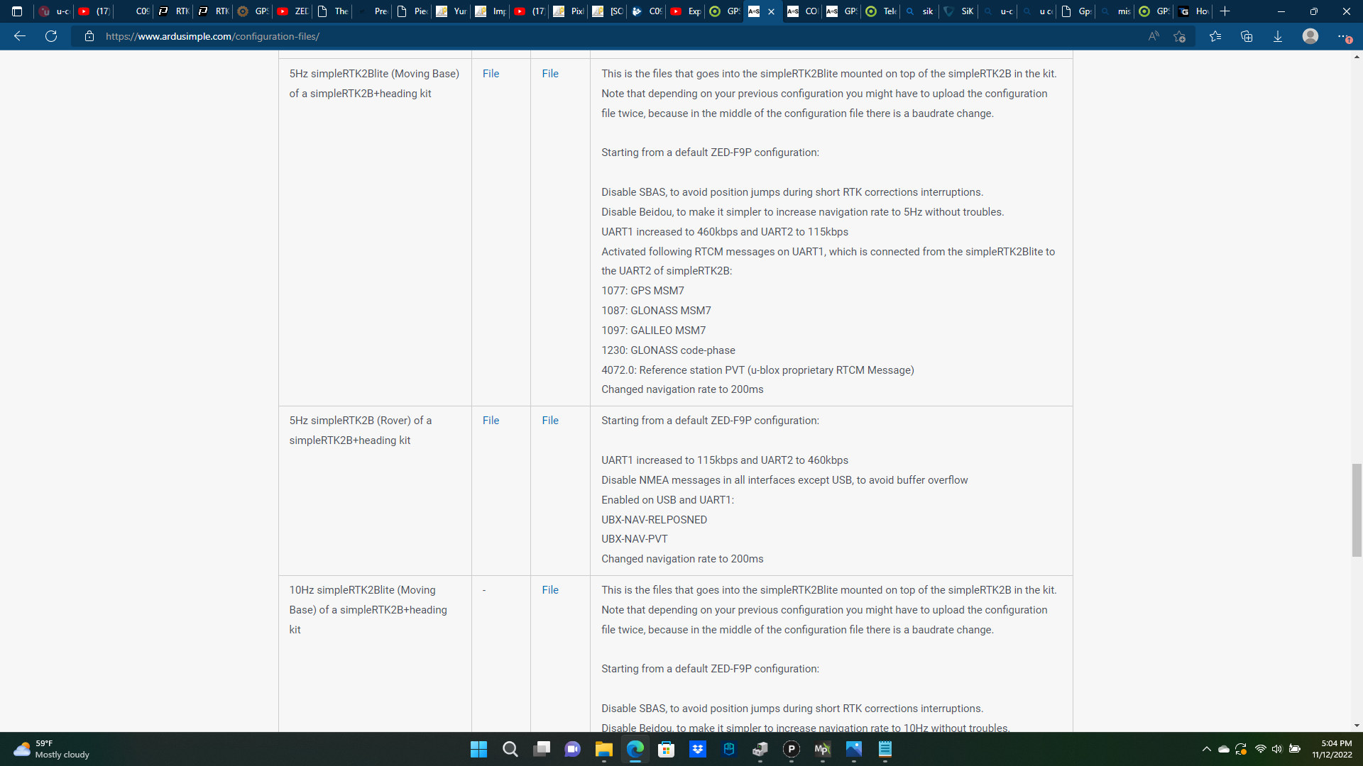
I’m looking at writing a tool to compare F9P config files and wondered if this would be useful or if it already exists. The config files save as HEX with Key/Value pairs and I’ve found a few LUTs that would let me do a quick conversion from HEX to readable values. You could compare a known default F9P config with say one that is auto configured from AP to see the differences.
Starting HEX Config File Example:
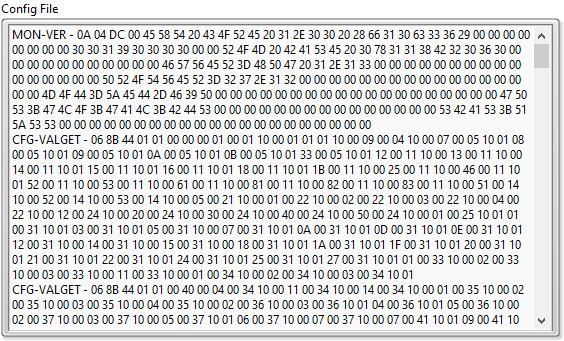
Readable Config Example:
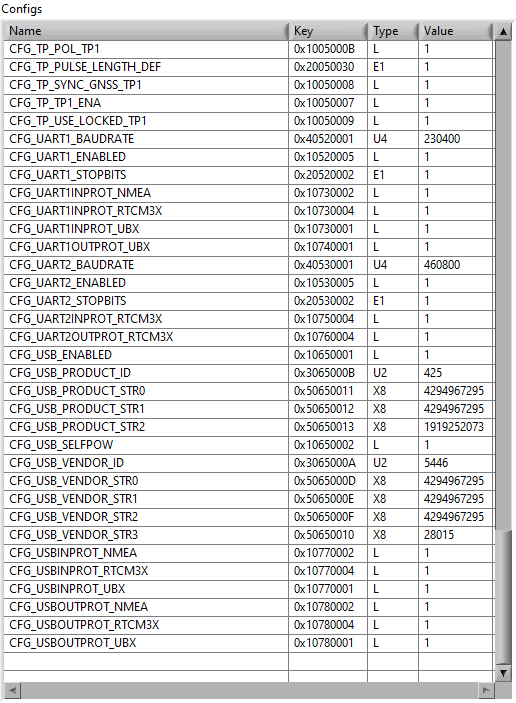
This list shows all the config parameters, but it could be filtered to show only the differences.
2 Likes
That looks to be a very useful tool and probably worthy of its own topic (or blog post when closer to completion).
1 Like