I’m afraid @GEOVANTHUMANITARIO’s topic is getting little traction due to the Spanish language title and content, but he’s asking a very relevant question, and I’d like to get him the help he needs.
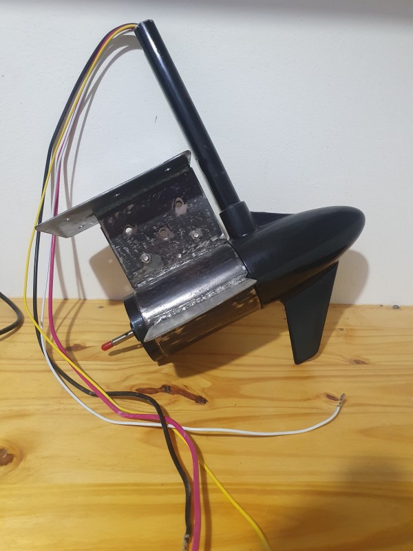
He’s building an autonomous boat in Argentina and is having a little trouble figuring out how to control a 12VDC trolling motor with ArduPilot hardware. I think it should be possible to wire a PWM based DC speed controller, but neither he nor I can determine why there are 4 wires coming out of the motor housing.
I assume red and black are power and ground, but can anyone help us understand what the white and yellow wires are for? A reversing circuit perhaps?
The motor is an “A Qualie” branded 55lb thrust trolling motor, and I can’t find much about that brand online.
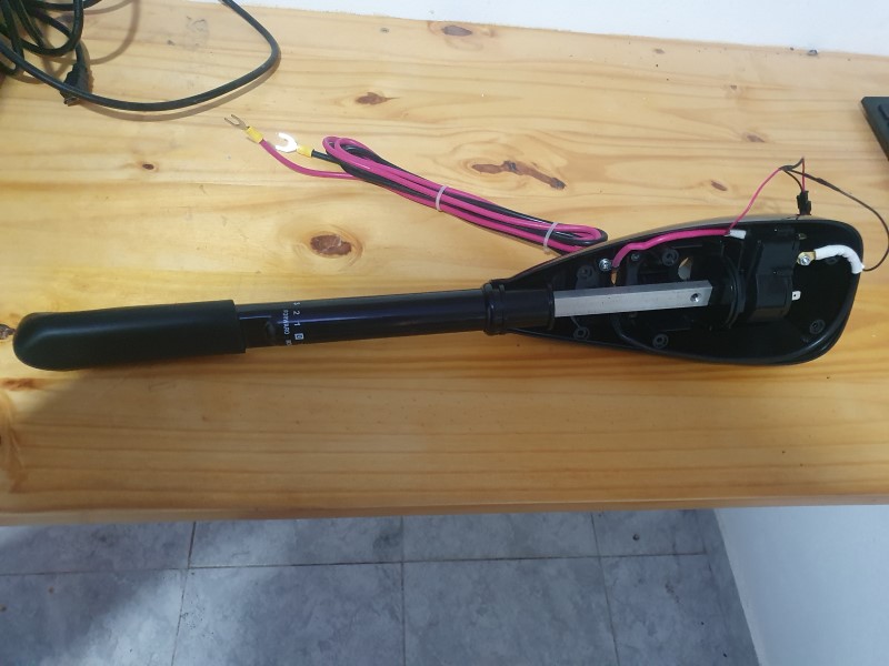
His alternate plan is to use a heavy duty servo to simply twist the throttle control on the motor’s handle, but that seems unnecessarily mechanically complex.
Googling “Trolling motor 4 wires” resulted in this:
It seems to be meant to either connect two batteries of the same voltage, one live and one backup, or two different voltage batteries (12 and 24V) for cruising and water skiing (just kidding). The article says there should be a selector switch somewhere.
Buenas tardes count74, te comento, el motor anda con una bateria de 12v 55 amperios o 75 amperios, aproximadamente unas 4 horas, con un peso de 200 Kg , asi que en el caso del USV calculamos misma autonomia o un poco mas, el motor tiene 4 cables, rojo positivo, negro negativo, amarillo y blanco q son de velocidad reducida, cuando pones el punto uno de inversa, el negro pasa a positivo y el rojo a negativo, igual los amarillo y blanco, conectando solo rojo y negro la velocidad es la maxima del motor, tiene la opcion de que tambien trabaje a 24 v pero no lo vemos viable, ya que le aumentariamos mas peso, se me ocurrio que poniendo un servo 360° que maneje el manillar para poder usar distintas velocidades, pero seria bueno si hay algun tipo de controlador inversor con ESC que se pudiera adaptar a este, las ESC que conozco yo solamente vienen con positivo, negativo y el cable de pulso, y a parte deveria poder soportar el voltaje y amperaje de la bateria , eso es masomenos la idea, el por que de este motor, la embarcacion tiene una manga de 3 metros y su ancho es de 0,85 ya que la idea es poder usarlo en aguas aviertas o turbulentas
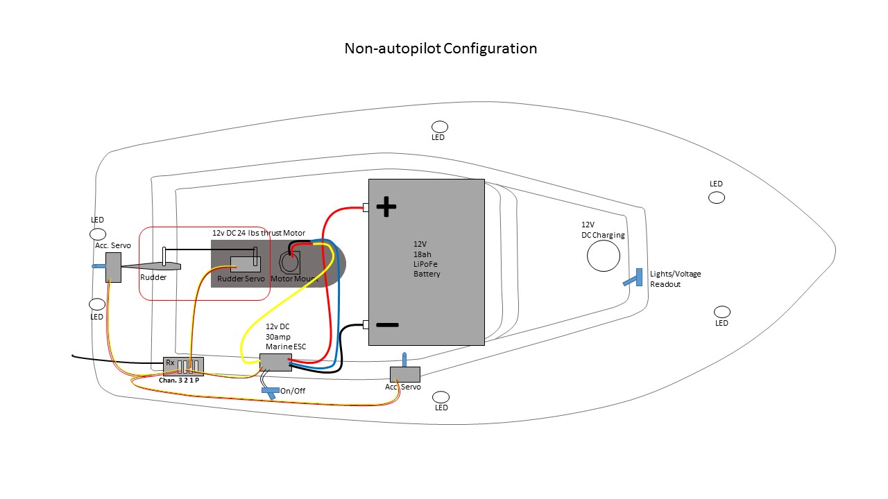
I had a similar boat using a brushed electric outboard (Brand name: Jarvis Walker). Similar to this installation, only the lower half of the outboard was used. As it was brushed, there were only two wires to contend with. These were connected to a 30A brushed motor ESC. Here’s an image showing the setup.
Hello Darren_Smith, I consult you, how to change the direction of rotation of the motor, seeing the plans that you sent the difference is that the motor battery is not lipo, it is a real boat battery, given its autonomy, and what type of ESC It supports only 2 cables at the output without the pulse, the Pixhawk will work with lipo, but the ESCs that I know do not work for this type of motor, I do not know if I explain myself well, please let me know if not Is that so or if there is any doubt.
Thanks Dave, and I’m sorry if I can’t explain or understand some things around there, according to what you say, the esc is the one that does both the ascent and the change of direction of rotation of the motor, the question is, what esc It is used for this type of motor that I pull cable for pulse, that is, I have only positive and negative cable
WILL YOU SERVICE THIS ESC FOR THIS PROJECT
Grupo Ni-MH, ni-cd 4 - 6 (4,8 V ~ 7,2 V );
Batería de litio 3 grupos (7,4 V-11,1 V)
Parámetros de corriente: Adelante 320 A, marcha atrás 160 A, freno 270 A
Salida BEC: voltaje 5,6 V, corriente 2 A (suministro de electricidad para receptores, servos)
Looking at the note of the tests carried out on a trolling motor, I see that the time capacity is approximately 15 minutes, since the lipo although they are light they do not provide much autonomy, taking into account that we require that it reach no Less than 3 hours of autonomy, unless you can put a car battery, or similar that reaches that autonomy, I explain a little so that I am not misunderstood, in most countries, although nothing is easy, Here there was a very large devaluation, to give you an idea, in the first place it is a country where nothing is achieved at all, in terms of technology for this type of activity, and what there is is very limited, second, a salary of commerce employee, which is the vast majority, does not exceed 260 USD per month, and today a Pixhwak controller does not cost less than 600 USD, I tried to bring from outside, but until now it has been difficult, a plate that comes out 100 USD you have to add another 100 USD of dispatch plus 100 U SD that the state charges taxes on imported goods, that is why we are trying to find the way around this project, which although it seems like a hobby we use it to search for people drowned in lakes and rivers, and we do it without receiving any compensation,
For the moment I see the option of seeing that a 360 ° servo rotate the speed handle is more viable, I hope that there may appear some other solution that we can access here, obviously thanks for the support and advice to all
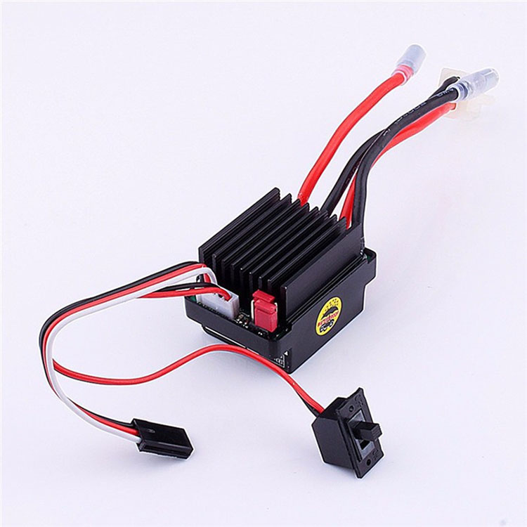
The ESC you show in the photo above may work if it has the current capacity. It looks like a common RC Car/Truck unit which is similar to what I have used in Rovers with brushed motors.
Yuri_Rage, I ask you a question, checking the file of your publication, apparently someone who may have the controller module, similar to those of basicmicro, could you tell me what would be the connection of the module to the pixhawk board and to the motor? And if apart from these elements I must add something else, thank you.
Yuri_Rage
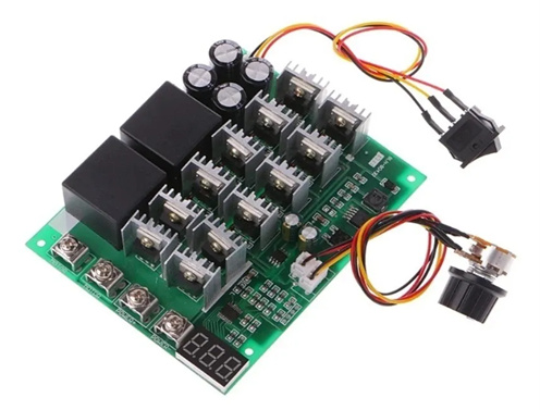
I found this controller, will it serve what I am building according to what we have been talking about?
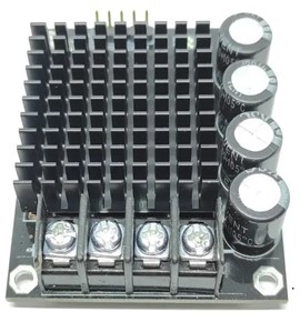
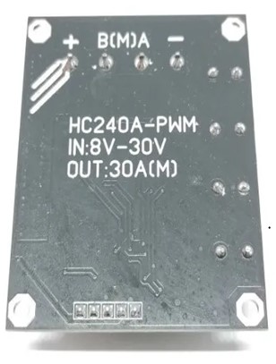
Regulator module features:
1 The basic components of the Regulator Module are patches, with high integration, excellent board design, very beautiful, small size, integrated, high-power single-channel DC motor. Regulator Module size is only 59mm * 49mm * 15mm;
The switching frequency is high, up to 60KHZ, effectively avoiding dissatisfaction caused by the low frequency of the debugging motor; It is recommended to use 2K to 10KHZ.
The control interface is very simple:
When A.B = 0,0 is the brake;
When A.B = 1.0, it is forward;
When A.B = 0.1, it is reversed;
PWM wave input (motor speed adjustment);
Pin-for common ground with the control board;
Pin + is a 5V200mA control voltage output,
4, 3.3V and 5V MCU can control this module
5, + and-terminals are power interface, M is motor interface. And you only need 1 channel motor power supply (limit voltage 8V ~ 30V)
3mm positioning holes are distributed into four, each gap is 52mm * 42.5mm;
That board might get you up and running, but I have two reservations about it:
First, the rated current is 30A, which might be too low for your motor. You could measure the peak current draw using a battery and multimeter to confirm the requirement.
Second, directional control requires logic signals on pins A and B. I don’t think ArduPilot natively supports that type of control, so this controller will likely work only in the forward direction when paired with a flight controller. You mentioned wanting to be able to reverse, which would require a different controller (or a more complicated interface to this board).
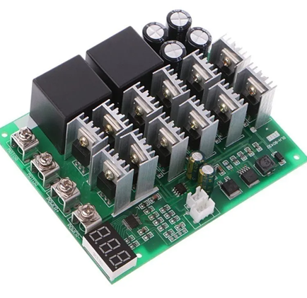
es, that module is small, here they gave me this one, I would value your opinion a lot, the worst thing is that you ask and none of those who sell them save anything, they are only importers and do not know the characteristics or what they are used for
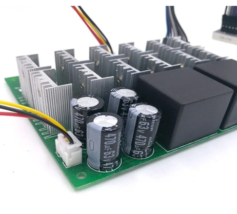
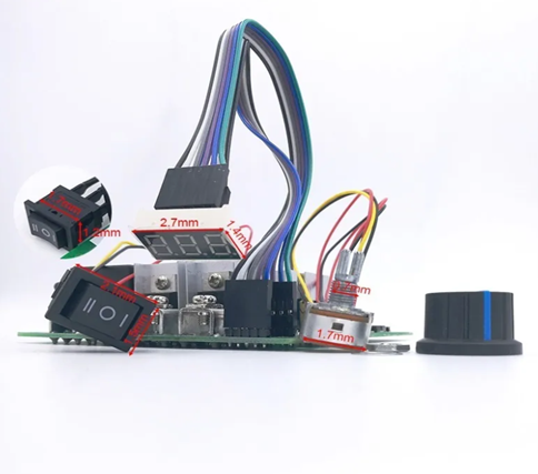
Pwm Speed Control Regulator For Dc Motors 60a
Regulator type: PWM
Minimum input voltage - Maximum input voltage: 10V - 55V
Minimum output voltage - Maximum output voltage: 12V - 48V
Maximum output current: 100 A
With adjustable output voltage: Yes