luweikxy
February 2, 2024, 1:34am
1
          if (!new_value) {
              // we don't have any new yaw information
              // slowly decay _omega_yaw_P to cope with loss
              // of our yaw source
              _omega_yaw_P *= 0.97f;
              return;
          }

          // convert the error vector to body frame
          const float error_z = _dcm_matrix.c.z * yaw_error;

          // the spin rate changes the P gain, and disables the
          // integration at higher rates
          const float spin_rate = _omega.length();

          // sanity check _kp_yaw
          if (_kp_yaw < AP_AHRS_YAW_P_MIN) {
              _kp_yaw.set(AP_AHRS_YAW_P_MIN);
          }
Why not use 3 axis of yaw_error?
	Vector3f error = Vector3f(0,0, yaw_error);

	// convert the error vector to body frame
	error = _dcm_matrix.mul_transpose(error);

	// ...

	// _omega_yaw_P.z = error.z * _P_gain(spin_rate) * _kp_yaw.get();
	_omega_yaw_P = error * _P_gain(spin_rate) * _kp_yaw.get();
?
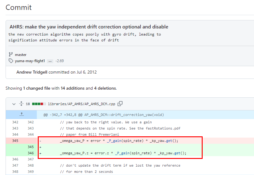
At here, I see that at begining, DCM code use 3 axis of yaw_error, but at this issue:
committed 05:11AM - 06 Jul 12 UTC
the new correction algorithm copes poorly with gyro drift, leading to
significat… ion attitude errors in the face of drift
, it was fixed to only use z axis of error with no clear explanation.
kd0aij
February 2, 2024, 3:29pm
3
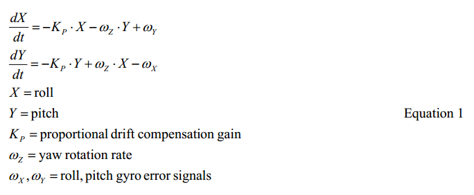
Here is the paper referenced in that comment:
luweikxy
February 5, 2024, 2:20am
4
I had post an issue, but was told that post questions on the discuss forums:
opened 07:46AM - 01 Feb 24 UTC
closed 08:40AM - 01 Feb 24 UTC
@priseborough @tridge
https://github.com/ArduPilot/ardupilot/blob/master/lib… raries/AP_AHRS/AP_AHRS_DCM.cpp#L576

Why not use 3 axis of yaw_error?
i.e,
```
Vector3f error = Vector3f(0,0, yaw_error);
// convert the error vector to body frame
error = _dcm_matrix.mul_transpose(error);
// ...
// _omega_yaw_P.z = error.z * _P_gain(spin_rate) * _kp_yaw.get();
_omega_yaw_P = error * _P_gain(spin_rate) * _kp_yaw.get();
```
?
This seems to lack a suitable reason to do so.
At here, I see that at begining, DCM code use 3 axis of yaw_error, but at this issue:
https://github.com/ArduPilot/ardupilot/commit/302696951a49da26d81ad4748d6aab1cdb7c84f2

, it was fixed to only use z axis of error with no clear explanation.
. So I go here.
luweikxy
February 5, 2024, 2:27am
5
Many thanks!
I have read this paper after you told me, I guess the reason is magnetometer has latency, so should not use magnetometer to fix x and y axis in body fame? I am not sure…
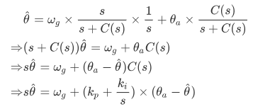
BTW, this paper is hard to read, for example, I can not figure out this formula:
kd0aij
February 5, 2024, 4:23am
6
He says equation 1 is derived from his DCM algorithm which is described in this paper:
It probably requires a fair amount of mathematical skill to duplicate his results…
luweikxy
February 5, 2024, 7:37am
7
I have read this paper several times, but it still hasn’t helped me in any way to understand equation (1)…
If only there were more mathematical derivation details…