What should I use for ATC_RAT_PIT_FLT* values?

Thanks for the information. I was not clear on what each new filter does.
One of the two was at zero after I updated and I had some trouble, so I made it the same as the other. I will try some lower values.

Is there more detailed information about these new filters somewhere, or can you briefly explain FILTE?

Indeed!

There are really about 6 filters that can be used to optimise performance.

The Gyro Filter is a 2 pole low pass filter that operates at the full data rate of the IMU and is used to remove the majority of the high frequency noise. It is particularly important because it must remove the majority of noise above half the PID loop rate (400 Hz by default).

The Dynamic Harmonic Notch. This is a series or notch filters that move up and down with the throttle setting or rpm sensor and in the future a real time FFT. We use this to further filter the propeller noise.

The Fixed Notch. This is a notch filter that is used to filter vibration mount, frame, or payload resonances.

Now we drop down to the PID update rate (400 Hz by default)

The FLTT filter. This is a single pole low pass filter. This filters the target rate coming into the PID object from the attitude controller. Its primary role is to filter the noise created by the lower update rates of the RC input and EKF bias corrections.

The FLTE filter. This is a single pole low pass filter. This filters the error term after the measured rate is subtracted from the target rate. I sometimes use this filter in roll and pitch if I have very large amounts of high frequency noise. In Yaw this is the primary filter and is used to replace the D term.

The FLTD filter. This is a single pole low pass filter. This is the filter used to prevent the D term amplifying high frequencies.

That is my go at an explanation of the relevant filters. I am not sure how I have done but I hope it helps. It might be worth going onto the Wiki somewhere if I get some feedback to refine it a little.

14 Likes

I think that’s a great explanation.
It has helped fill in the blanks for me, and I’m going to make a few adjustments to a copter I’ve been working on.

1 Like

With input from Leonard I’ve updated the tuning process wiki page to mention the new filters.

Hope that helps

4 Likes

Just a small clarification here. The gyro filter operates at the IMU backend rate which in general is 1Khz. The backend rate is a multiple of the IMU sensor sample rate which for fast sampling is typically 8Khz and for regular sampling is also 1Khz

D-term amplification is where smoking motors come from. Basically if too much gyro noise (controlled by the other filters but also the physical properties of your build) gets into the D-term filter and the D-term filter is set too high you will get noise feedback into the motors which they will not like very much. This effect can happen in a matter of seconds so when increasing gyro and D-term filters always check your motor temperature.

5 Likes

@Leonardthall What do you think about these crazy oscillations ?
It’s a X8 with 27"x8.8 props, 120KV (12S) max 12.3kg thrust per motor, 23kg AUW.

The same frame/motors/batteries, with a different ESC version flew fine with those parameters on <4.0.0 , this one can start to oscillate like crazy - I will have the owner to fix the filters, but it is hard to imagine they are the complete explanation to this occasional rodeo.

I’d advise running the Compass/Motor calibration too, check the instructions and stay safe!
ESC calibration was done?
Z axis vibrations are getting up a bit but not bad, maybe keep an eye on that.

These are a starting point, some are similar to your settings, but the Filters are different.

ACRO_YAW_P,1.30
ATC_ACCEL_P_MAX,27500
ATC_ACCEL_R_MAX,27500
ATC_ACCEL_Y_MAX,11700
ATC_RAT_PIT_FILTD,9.00
ATC_RAT_PIT_FILTE,0.00
ATC_RAT_PIT_FILTT,9.00
ATC_RAT_RLL_FILTD,9.00
ATC_RAT_RLL_FILTE,0.00
ATC_RAT_RLL_FILTT,9.00
ATC_RAT_YAW_FILTD,0.00
ATC_RAT_YAW_FILTE,2.00
ATC_RAT_YAW_FILTT,9.00
ATC_THR_MIX_MAN,0.10
AUTOTUNE_AGGR,0.05
BATT_ARM_VOLT,44.30
BATT_CRT_VOLT,42.00
BATT_LOW_VOLT,43.20
BATT_FS_CRT_ACT,1
BATT_FS_LOW_ACT,2
INS_ACCEL_FILTER,20.00
INS_GYRO_FILTER,18.00
MOT_BAT_CURR_MAX,50.00
MOT_BAT_VOLT_MAX,50.40
MOT_BAT_VOLT_MIN,39.60
MOT_THST_EXPO,0.79
MOT_THST_HOVER,0.20 <–initial low value, hover learn will fix it
PSC_ACCZ_I,0.50
PSC_ACCZ_P,0.25

After basic Testing and/or Autotune, you can set
ATC_THR_MIX_MAN,0.50
AUTOTUNE_AGGR,0.075
and run Autotune again - but depends how a craft of that size handles AUTOTUNE_AGGR,0.05

You can copy/paste those parameters into notepad and save as a .param file and then load it via MissionPlanner to save a lot of time and typos.

Thanks, @xfacta I see that you know what you are doing.
I already advised the owner to set _FILT to 10 where you have 9, and otherwise according to best practice, but still, I have a little bit hard to explain exactly what was going on.
From what I know, in wind & poshold it is more likely to happen, than in stabilize.

I suspect that your ESC is the problem. There is a large range or response time in ESC’s. In larger systems this is especially true.

Thank you.
How would you mitigate that effect?

If you change your ESC then you will need to retune your aircraft if you see any changes in performance.

What was the old ESC you were using and what is the new one?

@Leonardthall But of course it was autotuned, and could be flown quite well and aggressively.
But strong wind is kind of like kryptonite to it. :slight_smile:
The previous ESC’s were old Flame 80a (the ones that required external 5v to read PWM, and I made a redundant supply for each (diodes+polyfuses))
The new one is the new Flame 80A ESC , (self-supplied with 5v, according to manufacturer more linear performance.)
The older one could do some crazy things on strong wind, so can the new one, but it seems easier.
I suspect some interaction due to the coaxial nature of X8… but the overall performance is far from perfect.

Yes I saw the thrust curve of a new Flame and it looked like it had been linearised. This is the ESC manufacture trying to be too clever to cater for crappy flight controller firmware.

Your expo may be wrong. Do you have a thrust curve?

Hey @Leonardthall
I think It’s better to get full details from Tmotor for ESCs which have linearization and which do not. I have seen many in Ardupilot forum using flame and alpha ESCs and most of them struggle with this one question.
Probably add this detail to wiki. What do you think?
If you give me list of commonly used models, I’ll do wiki for them by asking details from Tmotor.

1 Like

yea that might help a lot if we listed the esc linearization.

I think T-Motor sell crap products at premium prices and they know their products have serious problems yet they continue to sell them with those known problems. It gives me a bad taste in my mouth to put T-Motor anywhere on the wiki. So what ever is on there should start with:

WARNING FOR T-MOTOR ESC AND MOTORS
ESC’s may have internal linearisation that forces you to measure the thrust curve if you want to get decent performance.
Motors tend to chew out bearings and will fly apart after about 100 hours of use.

But maybe that is my frustration showing.

Yes. I’ll do this. It’s long due. I see many guys facing issues because of ESCs.

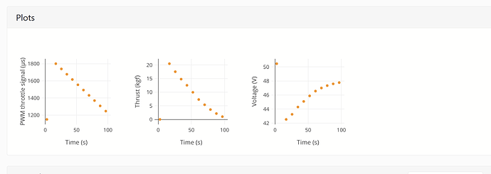
I currently have an aircraft using the T Motor Flame 180 ESCs with U13II motors and 32x11 props. Much as I would love to get a thrust tester, the costs are just prohibative and I can’t find someone able to test for me. The data I have seen on these ESCs on the RCBenchmarks website suggests that these ESCs are indeed linearised. So, rather than keep the standard value of 0.85 (as read from the graph relating to prop size), would I be better making a guestimate of somewhere between 0 and 0.2 as the Wiki now suggests? 0.16 for example? Also, should there be a note added on the ‘Tuning Process Instructions’ page of the Wiki to be aware of linearised ESCs rather than just going off the graph?


This is one of three tests that used the Flame 180 in the RC Benchmark database as an idea- it uses a U15 motor and 40 inch Xoar prop so quite a different setup to mine but it looks like linearised thrust to me???

I posted about this before.

Regarding thrust linearization of T-Motor ESC’s I’m not sure where this comes from. I inquired with T-Motor about this just a week ago asking about this feature with ANY T-Motor ESC’s and the reply from the Sales & Tech Department was:
ESC does not have this setting.
It is usually set by flight control.

Hi Dave, sorry but I havent seen your post on this as I only picked up on this issue whilst reading this thread,

I have also asked T Motor for their take on it so lets see what they say. With that said however the graphs above do look as if the T Motor ESCs do act linearly be that either by design or by chance. Just now need to work out the best MOT_THST_EXPO value to use now.