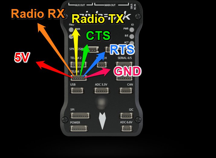
Would anyone be able to provide the Telemetry Port 1 pin layout for Pixhawk 2.1? Is it the same as the original Pixhawk or different?
A document is linked in this post: Telemetry Wiring
Does this give the info you need?
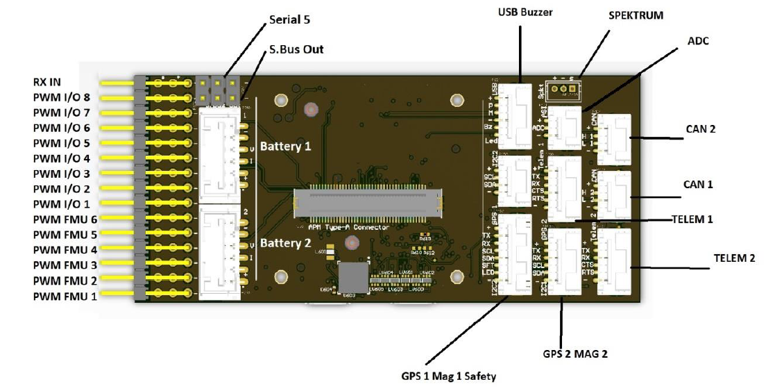
Yes, thank you! I believe this is what I’m looking for. It appears the PH2.1 telemetry connections are reversed from the original PH.
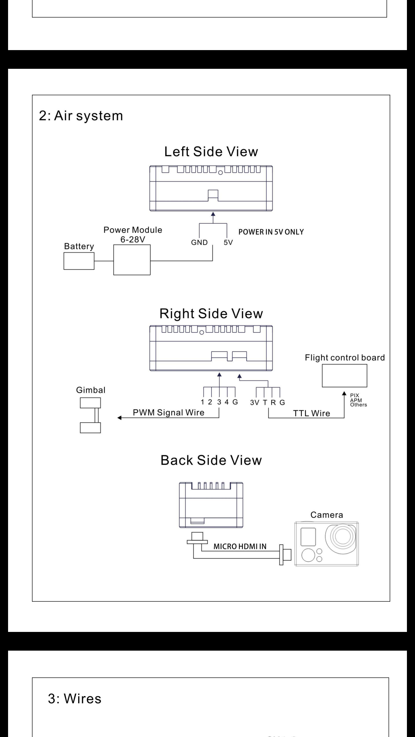
I purchased an Insight SE 5G 1080P 200mW Full HD Digital Video System. The Insight SE 5G has a 4 pin JST-SH port on it and apparently transmits telemetry data embedded in it’s video signal. I’m making a cable to go from the 4 pin JST-SH to the PH2.1 JST-GH telemetry port so that’s why I needed this info. One thing that caught my attention is the Insight SE 5G’s 4 pin JST-SH port lists a 3V power but I believe the PH2.1 provides 5V power? (It’s the “TTL Wire” diagram)
1 Like
Thank you for the help everyone! I was able to figure this out and now have both telemetry data and video feed going through the Insight SE 5G.
Hey there, how is the video transmission? Is the latency acceptable?
Hi Marcus, I’m doing this right now and have exactly the same question… is the 5v from the pixhawk going to be good or not/good the “3v” on the Insight drawing?
Also, the Insight cable provided for the tx unit has the black wire where it should be 3v pin and only 2 other cables TX/RX and no cable for the ground. It doesnt make sense really. How did you achieve it?