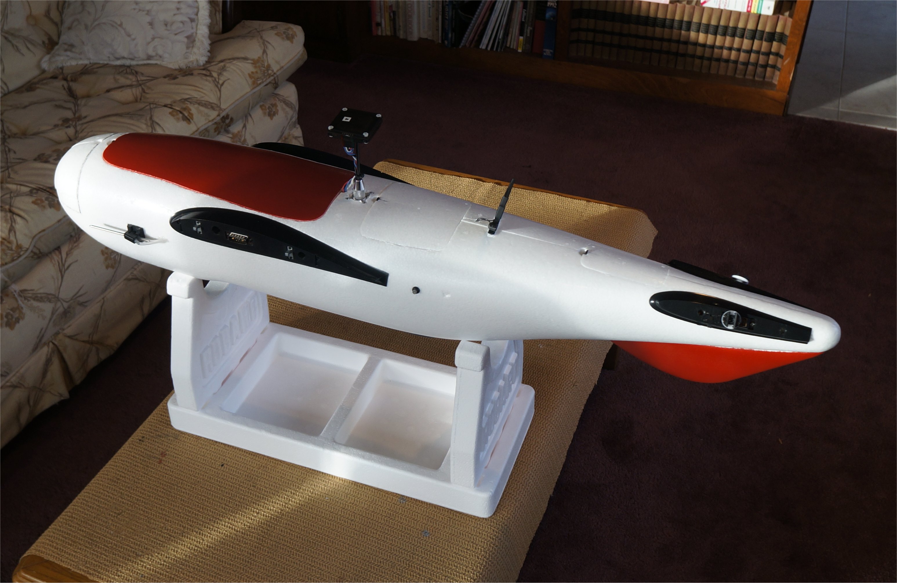
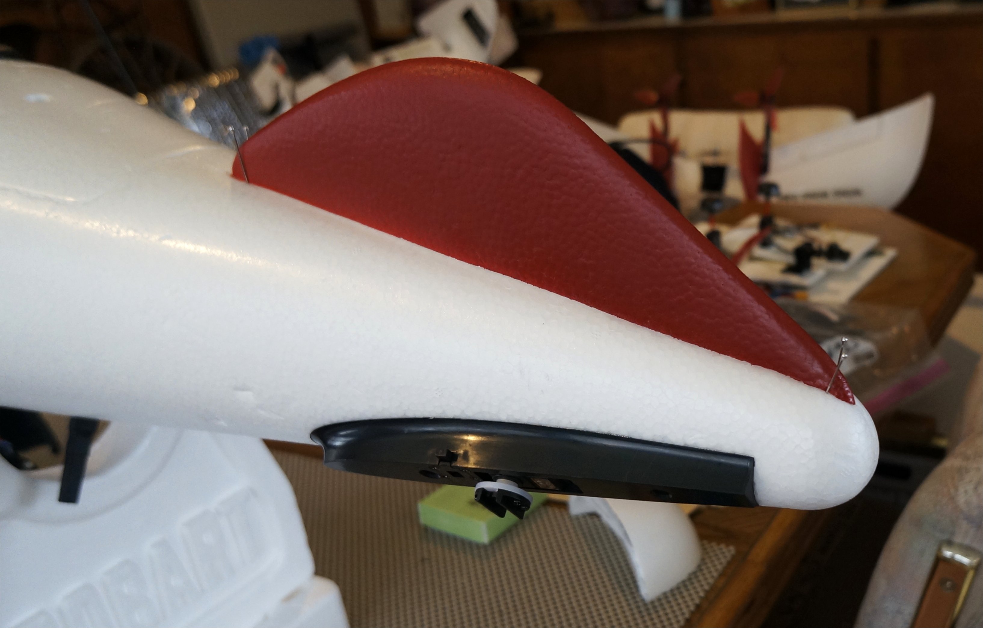
Along with my well-made load mounting bracket, I received a ventral fin. After checking that the fuselage would still go in the case properly, I decided to mount it. Over the holidays, I spray painted the fin along with the main hatch. The fin was glued in place using Foam-Tac. Instead of tape, I used pins to secure the exact spot while the glue dried. Perhaps the 2100 model doesn’t really need the ventral fin but it shouldn’t hurt and gives the Freeman a better look.
1 Like
We have finished out auto tune and are about to attempt a transition.
We are fine with the VTOL_TAKEOFF options and the basics of mission planning, but we would like to hear from others what flight profiles we should expect for VTOL_Land.
From the documentation:
When using NAV_VTOL_LAND it is important to have the right horizontal spacing between that waypoint and the previous one. As soon as the aircraft starts on the NAV_VTOL_LAND waypoint it will transition to VTOL flight, which means it will start flying much more slowly than it does in fixed wing flight. So you need to put the previous waypoint the right distance from the landing point. If it is too far from the landing point then the aircraft will spend a lot of time in VTOL flight which will waste battery. If it is too close to the landing point then it will have to stop very abruptly in order to land.
For most small QuadPlanes a distance of between 60 and 80 meters from the last waypoint to the landing point is good. For larger faster flying QuadPlanes you will need a larger distance.
We are wondering what sort of distance from the the last waypoint to the landing position we should be using for this airframe with out stressing it too much. Obviously we want to keep it as short as possible and have to factor in headwind, payload and altitude.
I use ~200ft, with a well loaded airframe. Anything shorter than that and it tends to overshoot, longer than that and it stops short of the point and then wastes battery by hovering around.
2 Likes
Thanks for that. That helps a lot. What kind of glide slope are you typically coming off when reaching the last waypoint? I have had good success when using a 15% gradient with the Believer and being able to maintain a decent airspeed. I think we may test that first.
I use a flat approach at 150 ft, all descent is done in the downwind and base legs. That way the aircraft doesn’t need to change attitude during de-transition. It probably is worth experimenting with, but I see no need to change my own way of doing it, as it works well.
We have been flying a lot of missions and a while ago decided to stop using auto take off and landings.
A few reasons for that:
- conditions may have changed. Wind direction or speed is not as expected anymore
- landing spot is not available anymore
- any other unforeseen reason
So we decided to use the following sequence:
Take off in Q-HOVER and ascent to 30~40 meter. Switch to FBWA and climb to mission altitude. Switch to auto and start mission.
After the mission, return to landing area. Descent to a comfortable altitude, useally around 100 meters. When the UAV is insight, switch to FBWA and descent further while preparing for the landing area. We usually descent to about 30 meters, nose wind.
Somewhere between 100 to 70 meters from the landing spot we switch to Q-HOVER. Our pilot likes to overshoot the landing area slightly so he can control the UAV, looking at the tail.
This way we have full control over the UAV during take off and landing. When something goes wrong, no need to switch to manual take over.
Of course we are licensed to fly long missions beyond line of sight and our pilot is also a licensed pilot.
We use ping ADSB receivers to monitor the airspace.
2 Likes
Hey Guys,
I am working on my Freeman build. I am making good progress and have a question for other builders.
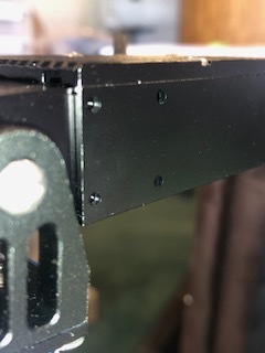
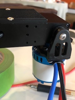
On the forward engine mount one side has five holes and the other side has four holes. I can’t figure out what they are for. After mounting the tilt servo and tightly fastening the four bolts, the tilt servo has a bit of vertical play in it, probably 1-2mm. I’d prefer seeing no movement in the tilt servo. I am wondering if I am supposed to use the holes to help secure the tilt servo. Please see the attached images.
Thanks,
Dave
Those holes are for mounting the tilt servos. Certain shape style of tilt/robotics servos will have holes that match those and let you put screws in.
Thanks for the quick reply.
I noticed that from Greg’s pictures above.
The tilt servo provided with the kit doesn’t have any holes in it. As far as I can tell there is only one way to mount the provided tilt servo:
The forward engine mount has a rectangular spline (can’t think of a better word).
The cutouts on either side of the tilt servo fit nicely over the spline
The top attaches with four bolts that provide downward force to keep the servo in place. It almost works. But the vertical movement of the servo isn’t good. The entire kit is very well thought out and everything fits together snugly, which makes me think I may be doing something wrong.
Pictures provided.
Thanks,
Dave
Hi Dave,
It’s difficult to understand your exact issue as your photos are too close and you appear to have a different version than some of us. Take a look a this Installation Reference and see if it helps. While the text is in Chinese, the images are universal. It appears that the cutouts are anchored to the “spline” with a few screws to remove your vertical movement.
Cheers!
Greg,
Thanks for the reply and the link to the Installation Reference. Surprisingly that didn’t come with my kit.
And my version of the Freedom is different from the one depicted in the manual. The images of the tilt servo do show screws securing the servo. I don’t see a way to do that with the provided servo. There are no holes in the servo to receive a nut or screw. I think the intent is to the lay servo mounting bracket over the spine and the downward force from the screws securing the top keep the servo firmly in place.
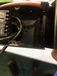
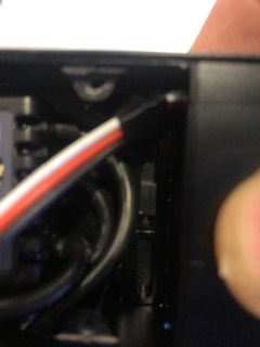
The photos were tight to show the spline on the motor mount and the holes in the side.
My exact issue is the tilt servo has too much vertical play. It probably moves up and down at least 1-2mm. It should be rigid.
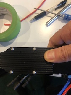
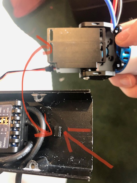
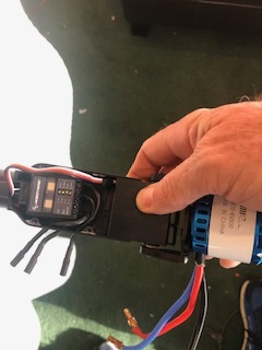
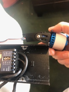
I attached a few more images. I hope they are more helpful.
Thanks,
Dave
There are
Ok, I see what they are doing now. I would simply drill some small holes through the metal plate into the servo casing and secure it with some small, short screws. Try not to drill too deep beyond the servo case.
If you like, you can tap the case holes and use machine screws or simply use some small wood screws that will bite into the servo case. This is how the other robot servos are set up. One side has machine screw holes and the other side has smaller holes for tiny wood or sheet metal screws. You can buy the hardware sets at various places.

Hi, if i’m not mistaken there are small screws on the sides of that servo. Just unscrew them, put the servo in the hole than the holes on the side should line up.
1 Like
Thanks.
Turns out that isn’t necessary. The obvious choice wasn’t the correct one. While the spline and servo mounting slots line up and fit snugly, that seems to be a coincidence. I rotated the tilt servo 180 degree, removed the screws from the servo case, aligned the holes in the servo case with the holes in the forward mounting bracket and re-inserted the screws. Fits really well with no movement. Very solid.
Dave
Thanks. That is exactly what I did.
Hey Guys,
I finally have all the wiring and soldering done. Now, I am working on setting up the pixhawk properly. All of the control surfaces are working properly but the engine tilt servos.
Relevant parameters:
Servo1 - 75 reversed, min 1000 trim 1500 max 2000
Servo2 - 76 reversed, min 1000 trim 1500 max 2000
Servo_Rate = 25
Q_TILT_MASK - 5
Q_TILT_TYPE - 2
The tilt servos are moving in the correct direction however range of motion is limited to about 30 degrees. When I choose manual flight mode the engines move toward horizontal but stop 30 degrees prior. Similarly, when I choose QSTABILIZE the servos move toward the vertical but again stop about 30 degrees short. The PWM output range from both servos is 1400 - 1600. Something appears to be limiting the commanded PWM output for each servo.
When I set Servo1 or Servo2 to 4 (aileron) I get full range of motion.
I am guessing I have one of my tilt parameters wrong but I don’t know which one and I have tried different values with no change to the range of motion.
As always, I appreciate the time and experience of the community.
Thank you,
Dave
1 Like
Hi David,
When you change the SERVOx_MAX or SERVOx_MIN value and the tilt servo does not change, it means that you have choosen the wrong x or that your SERVOx_FUNCTION is incorrect.
These settings can be defined however you want but they must also match your cable connections on the MAIN and AUX outputs. My examples posted above use the same setup as the Nimbus VTOL. See the diagram below… Others, like Wasim, use their own scheme so be careful if you are following an existing .param file.
FreemanBuild5_ASsensor.param (17.0 KB)

1 Like
Greg,
Thanks, I am pretty sure I have the connections and servo assignments correct. The tilt servos are connected to MAIN 1 and MAIN 2. Servo1 = 75, servo2 = 76. Both servos move when I change min, max or trim on the respective servo.
If both servos move when I change the flight mode to manual or qstablized doesn’t that mean everything is connected and assigned properly?
I am not using a third party param file.
Thanks again,
Dave
Dave,
I guess that I missed “the range of motion” part of your statement above. Something seems wrong. I’ll assume that you have tried values for MAX and MIN above 2000 and below 1000, respectively?
Make sure that you are not ARMed, only that you have the safety switch/button feature active to provide power to the servos.
Yep, I’ve tried that. The engine is at a 45 degree angle when trim is set at 1500. It’s not armed and safety switch is pressed.
The PWM output range seems limited to 1400-1600. What would cause that?