Thats actually what it will probably come to lol or maybe ill think of a way to make a coupler-esque feature. I wanted it to be able to be capable of disassembly so students can interact with it. Thanks for the advice though, Il mention you to my supervisors. Btw nice yuri camp profile picture
Yeah, I also wanted mine to be disassembled easily, but zip ties and glues are just too convenient to quickly explore and prototype. I published all my .stl but my design is hard to reproduce because it’s MY prototype. The design here SingleCopter of Benjamin Prescher on Ardupilot is truly a level above, and if it works well with ardu it could help the small single copter community here.
And please use my online presence as you wish. As long as people are asking interesting questions while looking for answers themselves and not just waiting for me to build their copter, I’ll surely help them (if I don’t miss their posts/messages).
PS : Gotta spread comfyness and the secret society blanket wherever I can.
I just wanted to point out that there are lots of different kinds of digital servos. I think it’s safe to say all hobby servos can receive a 50Hz control pulse. Some digital servos can receive much faster updates. Often the tail rotor of a helicopter will use a digital servo combined with a gyro which drives the servo much faster than 50Hz. These types of servos have much faster update speeds compared with other hobby servos. Many of these fast servos can’t be powered with 6V like other servos. The fast servos I use with my helicopter come with a 5V regulator to make sure the voltage isn’t too high. These fast servos need a corresponding fast drive signal. I think most flight controllers use the standard 50Hz signal to control servos. It’s possible this sort of thing can be configured in the flight controller. I know some ESCs can use fast protocols and many flight controllers can use these faster protocols so maybe flight controllers can also drive high speed servos faster than the standard 50Hz signal.
Analog servos generally have torque proportional to how far the current position is from the target position. If an analog servo only needs to move a small amount, it won’t use as much torque as if it has to move a large amount. Digital servos generally produce full torque for all movements. This also means digital servos generally use more power than analog servos.
Some digital servos have all sorts of extra features. Some can be assigned ID numbers and addressed with a SBus data line. These SBus servos can share a common data line.
I’m new to ArduPilot but I’ve used a lot of servos. Here’s a link to a hexapod which uses 24 servos.
BTW, very cool project. I’ve enjoyed reading everyone’s replies.
Thank you for the detailed response! I think we are getting an ESC donated that can step down the voltage to between 5-6V. That naturally timed blinking robot is amazing!
I would like to ask a question that has been troubling me about digital servos, sorry if its basic but i dont seem to grasp it. I tried asking on the arduino forum but was confused by the response. I had interpreted the difference between a digital servo and analog servo as : Both receive the same command signal from a receiver or arduino to change position. But a digital servo can output pulses that can control its servo motor at a higher frequency and change positions faster
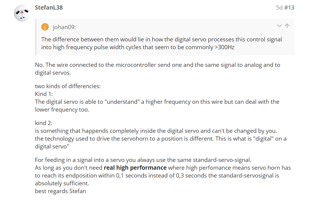
The reply i got was admittedly confusing on my end. I read this article before asking that question The Difference between Analog and Digital RC Servos - (radiocontrolinfo.com)
Thanks man  Il post some pictures if my professor allows it lol and try to contribute to the single copter community too!
I really like the reply by StefanL38. I’ve interacted that user on other forums and he has always provided great information.
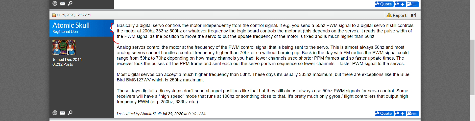
The “difference” diagram you posted is what is happening inside the servo. The internal electronics of a digital servo drives the motor with a higher frequency PWM signal. The internal frequency of an analog signal is the same as the 50Hz control frequency. The diagram shows the “kind 2” difference described by Stefan.
As Stephan said, if you don’t need real high performance, the standard 50Hz signal is fine. If you need higher performance, you’ll need to look at the specific servo’s datasheet to learn what sort of frequency it can handle. I don’t think there’s a standard “digital servo frequency”. You’ll need to find out from the servo manufacture how to take advantage of the specific digital servo’s unique features.
Edit: I should add than many digital servos don’t have unique features. They just use a microcontroller internally so small servo changes still maintain full torque. I think most digital servos don’t have extra features beyond the higher frequency internal motor drivers. Most digital servos should be driven the same as analog servos. They’ll just perform better (and use more power).
1 Like
He did reply to alot of me questions!
Ah yes it seems I posted signal inside the servo and not that sent to it by a receiver/arduino
Okay thanks! that power consumption is a bridge Il cross in due time lol.
I actually came across a thread just now that gave an explanation of the differences btw
That’s another good description.
1 Like
It really is! Thanks for the advice though