We are making an electric ducted fan rocket that uses a Pixahawk flight controller . In a way, it is like a single copter. The rocket thrust vectoring system uses digital servos for a faster response time. it has servo actuated flaps. We are using analog servos to actuate a parachute deployment mechanism in the rocket. We want the control both the digital and analog servos via pixahawk flight controller. I would like to know if using digital and analog servos might cause any problem.
I used shitty 9g analog servos, and it was alright. Some minor problem, that did not hinder flying, arose from the shitty servos but nothing that could only be fixed by changing the servos.
Thanks for the reply and I got to mention your single copter build looks impressive! I never owned a servo before so I was not sure how big of a difference using a digital servo compared to an analog servo would make. In your opinion, do you think it would be a significant enough improvement in response time to warrant the expense of getting a digital servo?
Digital servos differ from analog servos because they incorporate a microprocessor that analyzes the signal from the receiver and controls the motor. Actually an analog servo should always be faster, because that microprocessor time does not exist, but it is negligible.
The good thing about digital ones is that the same microcontroller makes them more reliable against signal oscillations, etc. But in practice, it doesn’t really matter for our purposes.
This is not a very technical opinion, but it can help you.
No, I don’t think getting a better (faster) servo will drastically improve the response time if that’s your goal. I used those black 9g servos. Did not used the cheaper blue because they kept breaking (the blacks break too, only the first gear is not plastic). The only complain I have about the servos is that there was some play that led to the servo self-oscillating because of the mass/inertia of the fins, but adding friction to dampen the oscillation fixed it (I explained that somewhere before).
What will determine your response time and stability is the amount and precision of torque you can apply. Longer fins and good mechanical structure was the limiting factor for me.
BTW, on this video without the oscillation fix, you ca see that my fins already move really fast everywhere. But this does not result in a rotation of the main frame. That’s also why I think better servos will not help the response time.
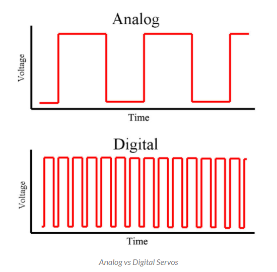
Thanks for the reply! I read somewhere that digital servos send pwm signals at 300Hz compared to analog servos at 30Hz so that led me to believe that response time will be faster. My thought was that by this, digital servos would be able to respond faster to changes. Like if it was at 60 degrees, and then quickly needed to move to 90 degrees , the higher pwm frequency of digital servos would be able to change positions faster. Although I’m not sure if thats what’s implied by the higher frequency of digital servos
Thanks for the reply Do you happen to have a link to that explanation? Is that related to the holding torque of the servo not being enough to handle the movement of the fins under the airflow?
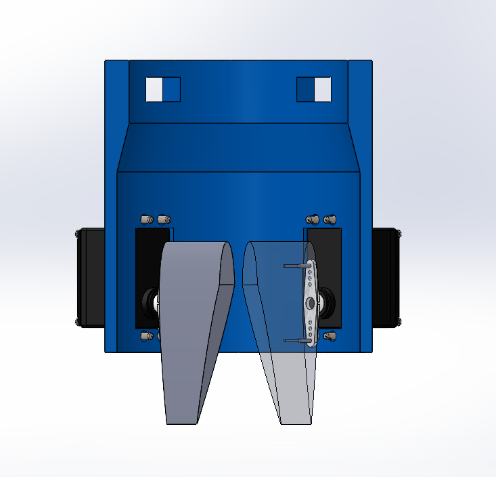
If possible can you elaborate on what precision of torque means? By the way, the fin setup is currently like so.
Servos vibration : because of the masse attached to the servos (a 18g fin) the servos tend to oscilate if there is no friction to dampen it. You simply need to add friction where you can to stop it.
It’s simply that the PID of the servo can be bad if your fin is heavy AND if there is some play. It gains speed one way, then can’t slow down to stop on the target, overshoots and repeats (this happens inside the servo, and that’s what is moving the flaps in the video I sent, nothing to do with ardupilot because it also happened unarmed). Play plays a big role in this, because the servo shaft can be static with the flaps still moving fast exactly around equilibrium, this is throwing off the PID of the servo.
But the torque of the servo is largely enough. If the servos were powered, and too much force was applied the inner gears broke, I broke a bunch of gears, but never while flying. (having spear servos from which you salvage the shitty plastic gear is helpful)
Sorry, precision of the torque doesn’t mean much. I mean the position of the fins, it’s not a problem of servo resolution, those are surprisingly precise. But the link between servos and flaps can f*ck it up, for example, the servo could move a very little bit to correct, but then because of some play your flap doesn’t move.
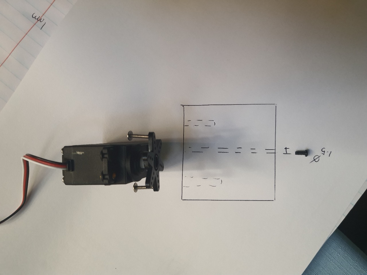
There is a + shaped piece that goes inside the 4 flaps and (pivot) link the 4 flaps together. This way no torque is applied perpendicular to the servo axle.
4Flaps-+piece-4servos are all pressure held together, pressure is provided by the fixation system of the servos on the main frame (ie a shitty zip-tie).
The downside of not gluing the flaps to the servo’s shaft is that you’ll have more play. But you can always glue my system.
Anyway, thanks for the picture. The Flaps will collide at the top, you’ve cut the downside but not the top above the rotation point. Also, be careful with the flaps touching the blue frame.
Also I like to have the flaps as low as possible, first this will increase torque.
Furthermore if you have some flap chunks above the rotation point/axis, this will reduce the flow on the wrong side of the copter and create small torque that will rotate the craft the wrong way. The part below the rotation point/axis will decrease the flow on the right (good) side of the craft. That’s hard to explain …
Imagine the bottom of you flap at full right, the main torque produced by the thrust vectoring is clockwise. But, the flap chunk above the rotation axis (of the flap) will reduce the flow on the left side of the copter, creating a small counter clockwise torque. The part below will create small clockwise torque (less flow on the right). That’s why I like having my flaps low if possible.
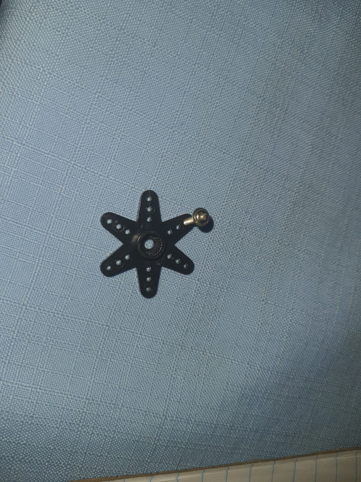
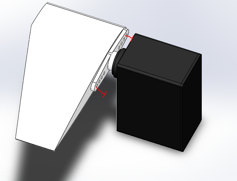
Okay now that you bring it up, im getting low ket worried about the servo to vane mounting lol. I intended on just mounting the vanes onto the servo horn via the screw that it comes with. Then just press fit the inner spline of the horn onto the outer spline of the servo
I think I get you. The longer the length above the rotation point, the more air hits that extended part and in turn (pun intended) causes slight rotation in the opposite rotation
With no screw or glue or constant pressure to hold the vane on the servo shaft/horn (sorry I don’t know the exact engineering word, I may know them in French) ? I don’t want to hinder your creativity, and maybe I misunderstood smthing, but that seems quite optimistic.
Ey i could use some sleep ngl.Ey thats what i thought at first, but if you check the upper blue image, the vanes need to be placed inside the tube. So like if you screw the horn onto the servo first, you wont be able to screw the horn onto the vane within the tube from the interior.
 Do you happen to have a link to that explanation? Is that related to the holding torque of the servo not being enough to handle the movement of the fins under the airflow?