I was able to run my first test with the RTK.
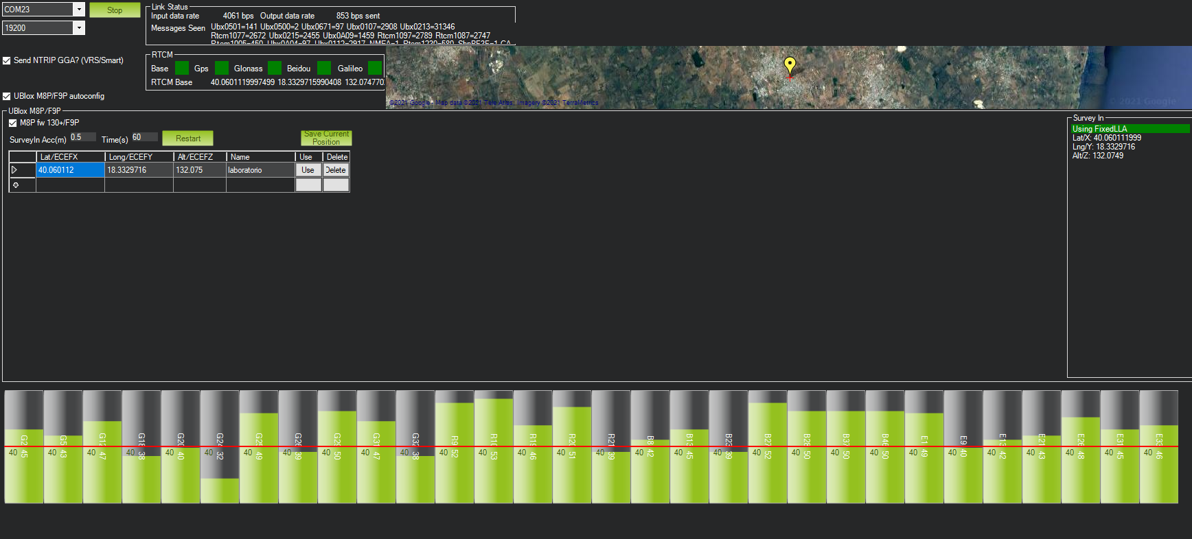
First of all, I configured the RTK Inject for the base station which is directly connected to my laptop via USB.
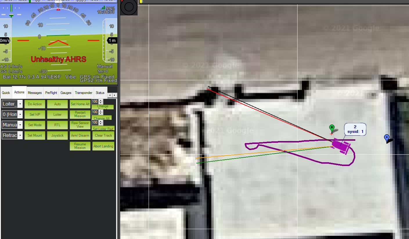
I always get “Unhealthy AHRS” and I can’t understand why since I should not use the compass anymore and the heading should be processed by only using the distance between the GPS modules.
I was able to export a dataflash log related to my first test. This is the log (I uploaded it on google drive).
Can you guys please check it and let me know if there are errors to fix?
I’m pretty sure there will be lots of things to fix!
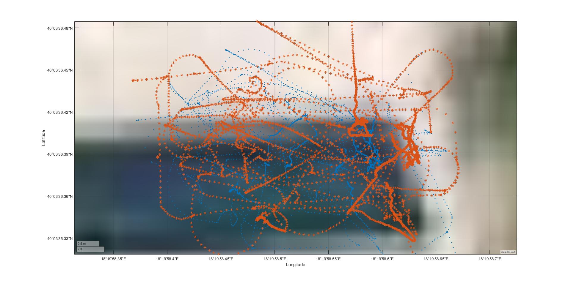
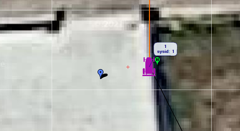
p.s. There is something that is not working fine since I tried to import a KML file in google earth and this is the result:
Since both modules are mounted on the same baseline (distance: 80 cm), I was expecting to have two parallel paths while from the picture it seems like the paths are totally random!
Hello guys, I know that it can be time consuming to read my recent posts since they are too long, but please try to help me since I’m stuck with these problems!
Thank you @Yuri_Rage ! You have reason, my bin file is 340MB and it is very huge, sorry for that.
I will try to run another short test and then I will upload the new dataflash log.
Do you think it is better for me to open a new topic for it or can I post the new dataflash log here?
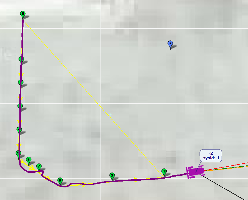
I’ve run another test with a short and simple path and this is the log file (34MB).
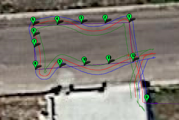
The first question would be: why the rover doesn’t follow a straight path but it always tries to “wave” around the waypoints? I was expecting to have the red line totally overlapping the path created by the waypoints.
Moreover, after having set up the base station by using the RTK Inject option, I can see the base station position on the map, but it is reported as “moving base” and not as “fixed base”: is it normal?
I’m not able to DISARM the rover and so I can’t download the log files from the SD card inserted into the pixhawk. Each time, I have to physically remove the SD card and inert it in my laptop. Every time I try to send the DISARM command from Mission Planner, I get “command failed”.
EDIT: I forgot to mention that since I still haven’t received the connector, I didn’t connected both GPS modules by wire and so I’m using Mission Planner to inject the RTK corrections to both the modules. I will receive the connector by tomorrow.
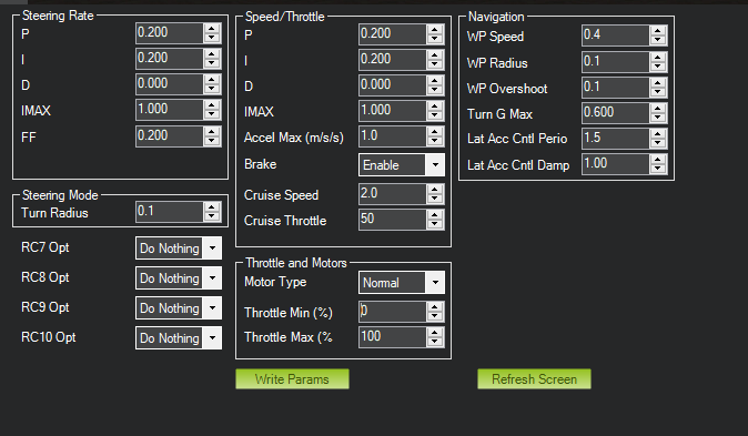
A newly configured vehicle will not typically perform perfectly without some additional attention paid to throttle, steering, and navigation control parameters.
Are you trying to use a moving baseline heading with both onboard modules getting corrections from the one source? The path that the vehicle has taken with respect to the waypoints is fairly typical of a newly set up rover that needs tighter control tuning to allow more aggressive navigation
Tomorrow, I will carefulyl check all the parameters for the navigation and I will run again another test!
However, this doesn’t explain why I’m not able to disarm the rover. Do you have suggestions about that?
@jimovonz: I have a fixed base station and I’m trying to use it to send the RTCM3 corrections to both the modules I have mounted on the rover’s frame: GPS1 as moving baseline base and GPS as moving baseline rover for GPS YAW.
Unfortunately we moved away from using AP about a year ago so I am not up to play with the intricacies of the latest code and can not comment on arming/disarming the rover…
With regard to using moving baseline for heading - this requires that the baseline is fixed with respect to the vehicle frame of reference. RTK enables a ‘rover’ to accurately determine its location with respect to the base station providing its corrections (which can then be offset using the base station coordinates to provide an actual location). Because the offset from the base station is known, the heading to the rover can be determined - note that this is the heading of the base line directly from the rover to the base station. In order for us to determine the heading of the vehicle, the corrections fed to the onboard rover module need to come from the onboard base module otherwise your heading vector will always just point to the static base station…
Thank you, @jimovonz! I guess my dual gps configuration is fine since the heading seems to be correctly calculated by looking at the previous picture.
Do you think I need additional modifications to improve it?
I think you have the moving base configured correctly and simply misstated the fixed base correction comms. If GPS2_RAW.yaw is reporting heading, there’s nothing left to do there.
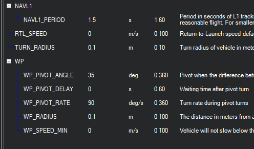
You should be able to do way better than that. WP_RADIUS is probably too small, and your NAVL1_PERIOD is too short. Increase the radius to 0.5 or so and the period to 5-8 seconds.
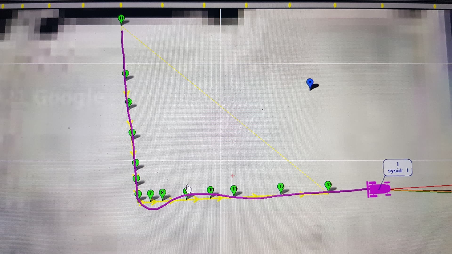
There is no need for multiple waypoints in a straight line like that. Delete the redundant ones.
I was putting all that waypoints on a straight line because I was thinking that would improve the accuracy of the path since the vehicle will have to move in vineyard rows and it will have to move very straight since the rows are narrow (their width is about 1.5 meters while the vehicle has a width of 0.75 m). But if it is not needed than I’ll remove all the redundant points, thank you!
The period was initially set at 8, but the vehicle waved a lot along the waypoints so I increased it and it waved more. I started to decrease it step-be-step to obtain a straight path between the waypoints. If set it back to 5 or 8 seconds, than it will start to wave again, unfortunately!
I increased the radius to 0.5 and tomorrow I will do additional tests on the field.
I aborted the mission after a while because I saw that the vehicle was waving a lot.
EDIT: I noticed that when I control the vehicle by the transmitter and I try to turn on the spot, sometimes, it happens that it suddenly change the turning direction. I don’t know if this can help.
Unfortunately I am going to give some conflicting advise here… I always aimed to have the NAV_L1_PERIOD as low as possible. This value determines how far ahead the vehicle is aiming to get back to the line between way points. A large value will cause it to aim for a point on the line connecting way points further ahead of its current position and thus produce a ‘lazy’ attempt to return to the path. Low values cause the vehicle to attempt to stick to the path more aggressively. The limiting factor is the vehicle ability to follow steering commands and if the value is too aggressive, it can cause overshoot and oscillations about the path. https://ardupilot.org/dev/docs/rover-L1.html
You can see here that the L1 distance is calculated as 0.3 x damping x period x speed
With a WP_RADIUS of 0.1, the vehicle must be almost on top of the way point before attempting to turn to the next one. I am not sure what the steering limitations of your vehicle are, but you must consider this when planning. If you want tighter turns (and you vehicle is capable of them) then you need to make sure your settings allow these tight turns and that the the WP_RADIUS is set so that it doesn’t turn too late. Obviously a pivot turn would allow following the course most precisely.
We had a number of different types of large, purpose built, agricultural vehicles running AP and managed to get our average cross path error < 0.05m on long runs. We also have vehicles that operate in vineyards but have moved towards lidar based SLAM combined with neural network based row following steering control.