Today, I updated the firmware on my two F9P modules from v1.12 to the latest v1.30 and then I changed the configuration on UART2 on both modules.
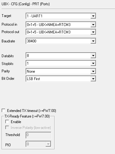
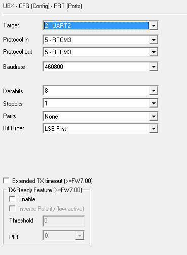
I set the baudrate for UART2 to 460800, but I wasn’t able to change it to UART1 and it is still 38400. Is it mandatory to change also the baudrate of UART1?
and I also enabled the following messages: 1005,1074,1084,1094,1124,1230 on UART1, UART2 and I2C on both modules.
Is my configuration OK or should I find a way to set also the baudrate of UART1 to 460800?
I will connect a wire between both UART2 ports to inject the RTCM3 corrections from GPS1 to GPS2.
So should I also reset the settings on UART2 for the RTCM corrections?
If I use GPS_AUTO_CONFIG, how can the GPS2 understand that it will receive RTK corrections on its UART2 port from the GPS1? Shouldn’t I enable the RTCM3 protocol on UART2?
@marcusbarnet I think that the part you are missing is that Ardupilot can relay RTCM messages between the two F9P modules. For this GPS_AUTO_CONFIG to work, each module needs to be connected the to flight controller via the modules UART1 (no direct connection between the modules is required). Ardupilot takes care of the config of both modules and forwards the RTCM data from the base F9P to the rover F9P.
GPS_AUTO_CONFIG = 1 → Enable automatic configuration for Serial GPSes only (hope it works also on pixhawk 5X)
GPS_DRV_OPTIONS = 1 → Use base station for GPS yaw on SBF (should it be -ublox-?!)
I just can’t understand if I still need to connect UART2 from GPS1 to UART2 on GPS2.
It is imperative that the rover and moving base communicate directly with one another, with the moving base providing RTK injects directly to the rover using the boards’ built in UART 2 ports. The flight controllers do not provide enough bandwidth/processing time for those injects to be passed through the controller successfully and at a high enough rate to support GPS yaw.
My ugly solution is pictured here. I wasn’t sure if it was going to be permanent (or even if it would work), so I soldered some female headers onto the UART 2 (TX2/RX2) pins of each board, and then secured jumper wires with some hot snot. They are the green and white wires pictured.
You simply connect TX2 from one board to RX2 of the other, and vice versa. ArduPilot’s GPS autoconfiguration should take care of the rest, so there should be no need to use uCenter to configure the ports directly.
Is it correct?
However, I have a pixhawk 5X and it provides two ports: GPS1 with 10-pins and GPS2 with 6-pin connector and my two F9P modules are connected to these ports at the moment.
My configuration should be:
Base station placed at a fixed position on the field → First F9P module as moving base → Second F9P module as rover.
If you use GPS_DRV_OPTIONS=1, you MUST connect the two GPS modules via their UART2 ports (which is what I thought you intended to do from the start).
If you prefer that all of that traffic be routed through the autopilot, then set GPS_DRV_OPTIONS=0. In that case, you do not need to wire the two modules directly together.
and without doing anything else, I will just have to inject RTCM3 corrections from my base station to autopilot by following these instructions (Here+ RTK GPS — Copter documentation), is it correct?
Sorry - I did sort of jump in there. @Yuri_Rage is correct with regard to GPS_DRV_OPTIONS settings. However, I have used the GPS_DRV_OPTIONS = 0 settings with no direct connection between modules on multiple vehicles with no heading issues (I have been using a moving baseline setup with F9P modules long before it was suported by Ardupilot with my own custom code - including direct connection of the modules). The RTCM data represents approx 1% of the bandwidth of the serial port and I do not see any advantage to the extra effort required to connect the two modules directly.
As long as the F9P firmware is 1.13 or better, I agree that there is little detriment in passing the data through the autopilot. I still use GPS_DRV_OPTIONS=1 because it is fairly easy to set up.
And if the F9P firmware is out of date, it should really be updated! There are lots of known issues with legacy firmware for that module.
For the moment, I think I’ll first try to use the cable between both UART2 ports and I’ll will let GPS_DRV_OPTIONS=1 to handle the settings on both modules.
I updated both modules mounted on the rover to [ZED-F9P HPG 1.30 firmware] released on 23-Dec-2021.
Tomorrow, I’ll update the base station with the same firmware.
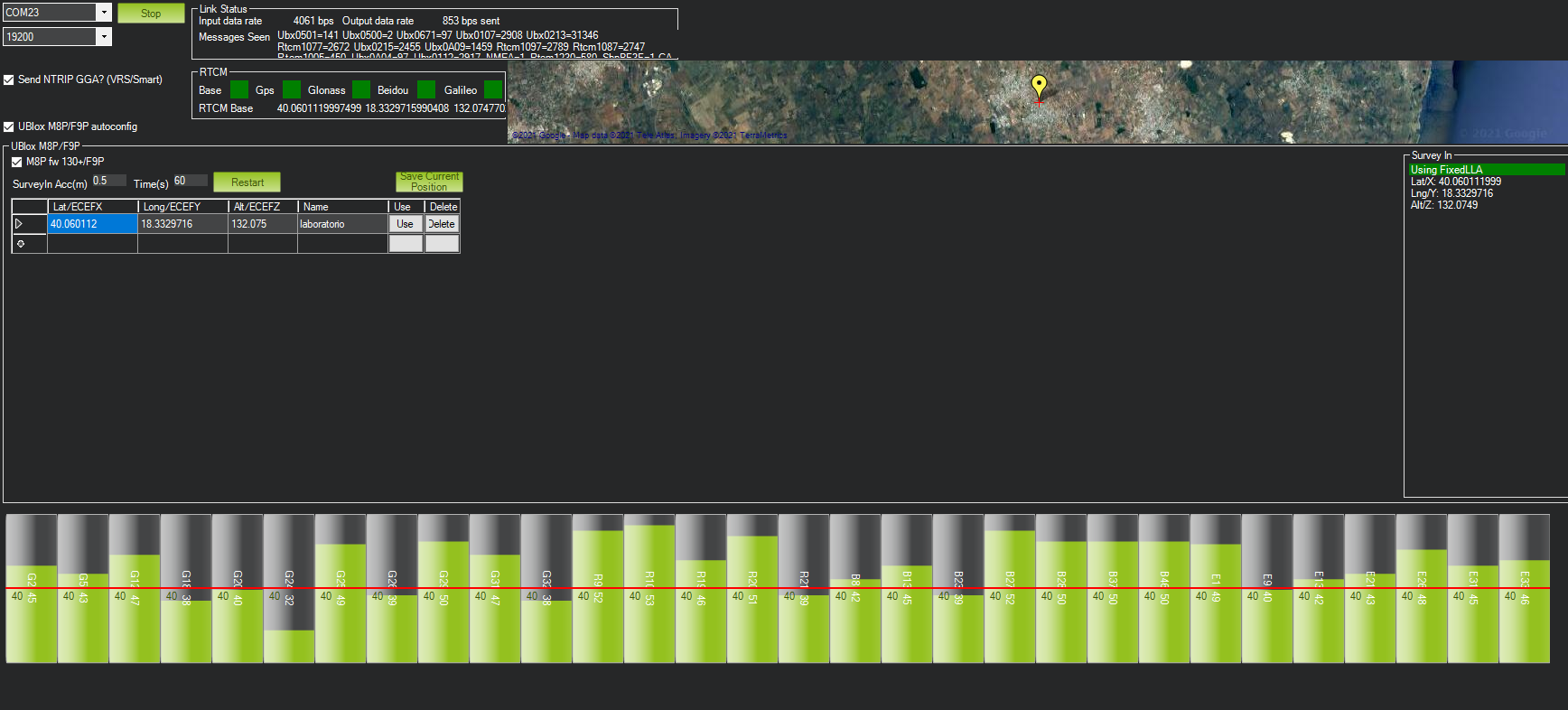
I was able to run my first test with the RTK.
First of all, I configured the RTK Inject for the base station which is directly connected to my laptop via USB.
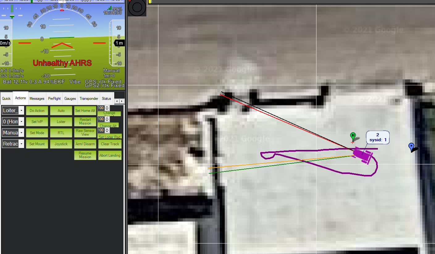
I always get “Unhealthy AHRS” and I can’t understand why since I should not use the compass anymore and the heading should be processed by only using the distance between the GPS modules.
I was able to export a dataflash log related to my first test. This is the log (I uploaded it on google drive).
Can you guys please check it and let me know if there are errors to fix?
I’m pretty sure there will be lots of things to fix!
p.s. There is something that is not working fine since I tried to import a KML file in google earth and this is the result:
Since both modules are mounted on the same baseline (distance: 80 cm), I was expecting to have two parallel paths while from the picture it seems like the paths are totally random!
Hello guys, I know that it can be time consuming to read my recent posts since they are too long, but please try to help me since I’m stuck with these problems!
Thank you @Yuri_Rage ! You have reason, my bin file is 340MB and it is very huge, sorry for that.
I will try to run another short test and then I will upload the new dataflash log.
Do you think it is better for me to open a new topic for it or can I post the new dataflash log here?