Continuamos con el desarrollo de el sistema de asceleracion y cambio de giro de la helice para el USV, viendo que en el mercado no hay nada compatible, optamos por ver si es viable el uso de un servo 360° que gire el manillar original del motor para realizar los cambios de velocidad y la marcha inversa, aclaramos, el motor es un omotto electrico de 12v 55 lbs de los que se utilizan en los kayaks para usar con una bateria standar de carro de calle, ven factible la idea o que sujerencia dan ?
My Spanish is a bit rusty, so forgive me for answering in English.
If I understand correctly, you want to use a servo to rotate the handle of an outboard/trolling motor to control its speed and direction. ArduPilot makes that very easy.
For many applications, an ESC is used to convert autopilot throttle PWM to a motor speed control signal. In your case, you’ll just use the throttle PWM output to directly control a servo.
That is exactly how I control the drive units on my ArduPilot controlled lawnmower.
gracias por la respuesta, la idea era que solo mueva el interruptor de cambios de velocidad, la direccion seria accionada por un timon, el por que de usar este motor es que la embarcacion tiene 3 metros de manga por 0.85 de ancho, es un proyecto humanitario, y lamentablemente aca en Argentina estamos limitados con la tecnologia, calcula que para traer una placa que salia 10 USD nos cobraban de flete 390 USD, una locura, pero bamos avanzando lentamente pero no perdemos la fuerza, en esto soy muy nuevo y para mi es dificil , es mi primer armado y seria un honor si me pudieran guiar, el motor este, es muy distinto a los usados para hoby, y no tiene cable de señal, lo cual hace que aca ningun tecnico me haya podido ayudar y me dicen q abandone el proyecto
Can you provide pictures or a link to the motor you are using? Also, a picture of its installed location?
It may be possible to wire a speed controller directly to the motor, but that will require some knowledge of its internal components. Otherwise a servo on its speed control handle should work just fine, as you suggest.
I think the solution will be somewhat simple, we just need a few more details.
Aca te paso los link para que puedas ver las fotos, no me deja subirlas al foro, cualquier cosa me decis, si queres el contacto es +5492392440649 para watsapp sino como CM Drone en face, como lo prefieras y mas comodo te quede .
https://drive.google.com/file/d/10WfW6n_H6-p1RD0dtwV1oR5_CuQ31wM1/view?usp=sharing, https://drive.google.com/file/d/12Az8IVG5W4K8oIWN2jbE8U5SF8WTZUl-/view?usp=sharing, https://drive.google.com/file/d/193EoPTPvRwJ7xi6-GVjqo3ru7cZ2b4YD/view?usp=sharing, https://drive.google.com/file/d/1GeL8h8F8HY4cbD9jKrcfIGh7DbVKp_xC/view?usp=sharing, https://drive.google.com/file/d/1IncPPpNrnzLheWR7Tlu7J0sgNhjF63Xy/view?usp=sharing, https://drive.google.com/file/d/1uWJUdk5QRVriopzVQmBgPub_eYG2Xs_U/view?usp=sharing
I cannot view the Google Drive links - they are blocked from public view.
Disculpa, a ver si ahora te permite verlas, https://drive.google.com/drive/folders/1M_ddph-dPprNiwL1eyenLjRLx586GMf9?usp=sharing
Hi Christian,
When you turn the handle on the original controller, does it rotate smoothly with the motor speed increasing proportionally? Or does it rotate to discrete positions and the motor speed follows in discrete steps?
I’m trying to determine if the controller is actually providing the motor with PWM proportional to the handle’s position, or if it is just a rotary switch. If the latter is true, the 4 wires may be switching between series resistances to control the speed. Maybe something like this:
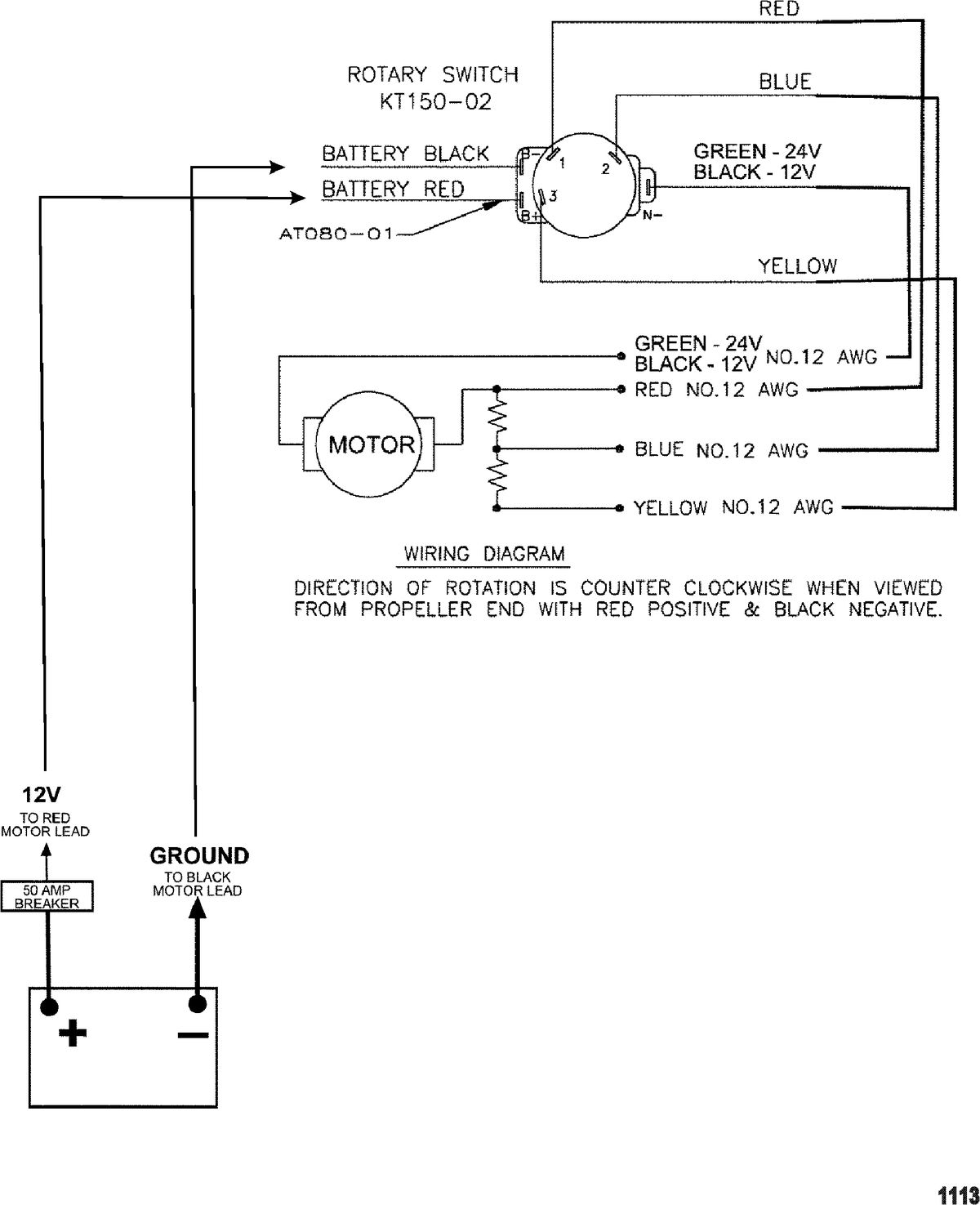
If that’s the case, you should be able to just use a standard brushed DC controller across the red and black wires and ignore the other two. To test the rotary switch theory, you can use a multimeter to measure the terminals of the controller with the rotary switch in different positions. The motor doesn’t have to be connected. You should see voltage (with a battery connected) or continuity (with no battery, doing a continuity measurement from battery + to the motor terminals) step between the contacts as you rotate the handle.
You should also be able to measure increasing resistances across the motor with respect to the black cable, with the red cable being the lowest resistance.
If it turns out that it is not a rotary switch and is in fact a PWM based controller, you’ll have to look into the white and yellow wires a bit more. Could be speed feedback to the controller or some other sensing function.
Hola, cuando giras la manija va por puntos, 5 hacia adelante y tres atras, con una traba leve entre punto y punto.
si conecto el rojo y el negro solamente a una bateria va a velocidad maxima, y si los invierto, gira hacia el otro lado, el amarillo y el blanco son velocidades intermedias, pero como el motor es una unidad sellada no se adentro que hay,
creo que la opcion de un controlador de CC podria ir bien, siempre que resista los 12v y amperaje de 55 o 75 amperios, vos tenes algun ejemplo de esa controladora para ver si la puedo conseguir aca? , por lo menos para ir avanzando con eso, por otro lado estuve viendo las controladoras pixhawk, y veo que hay muchas diferentes, este modelo tendria que abarcar aproximadamente 5 km de distancia para que sea efectivo y comodo a la hora de operarlo