So far this blog series has been involved with the mechanical aspects of the UnATRaP platform and while these are as important here as in any mechanical system, electronics have a very significant role in robotic platforms. We started touching on the topic last time with the power supplies and today we proceed to the core, discussing autopilot and avionics.
During the design phase, the idea was to have a semi-permanent installation of the core electronics in a dedicated compartment/bay, separate from any interchangeable payload. We selected the cavity at the back of the cabin, because it had a clean rectangular shape but also was the least accessible location of the cabin.
The Porter has a fairly tall interior; should we lay our electronics flat on the floor we would waste a lot of internal volume. For that reason, we went for a vertical layout of the various components.
A Nice Rack
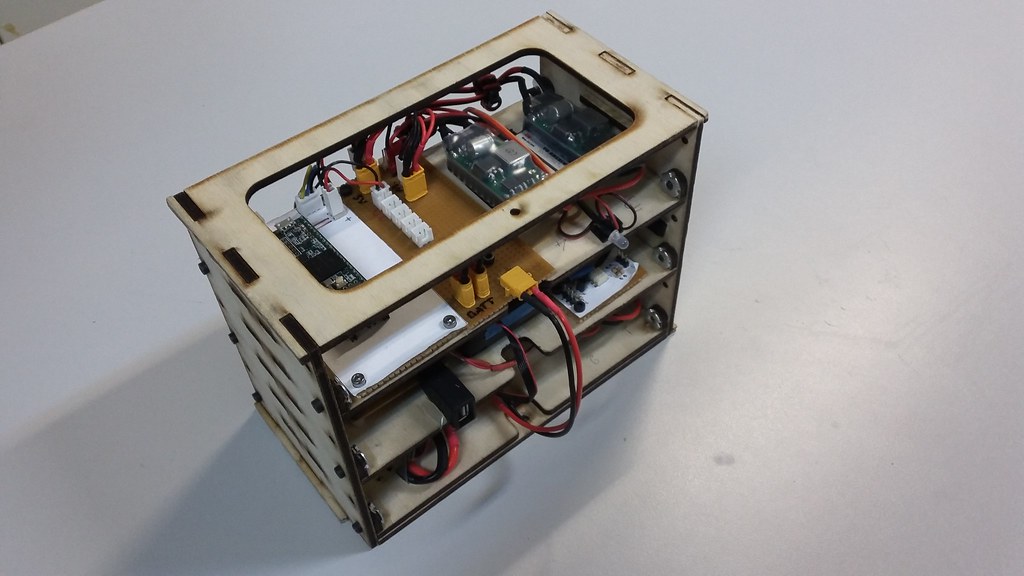
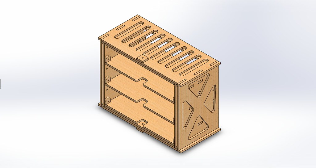
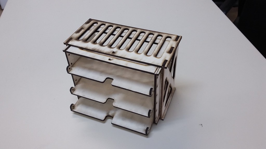
We wanted to go for a rack-like solution, which should be firm but at the same time removable, for ease of access in times of repair and upgrades. It should have independent shelves so each could host a notionally separate part of the circuit. With our favourite material (plywood) and our favourite tool (laser cutter) we designed and built the autopilot rack.
The plywood parts were assembled with CA glue. Each shelf can slide inside the rack and is individually screwed in place with hex screws and blind nuts.
Groundwork
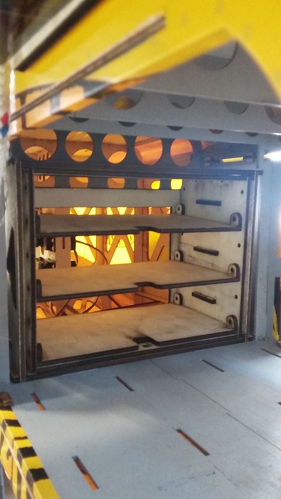
For the rack to be removable, glue or nails were out of the question as mounting options. Instead, we built an enclosing rectangular structure, which would be permanently mounted on the back of the cabin. The electronics rack can slide in and out of it while maintaining alignment with the airframe body axes.
The final position is fixed with two hex screws, going into embedded blind nuts.
The Shelves
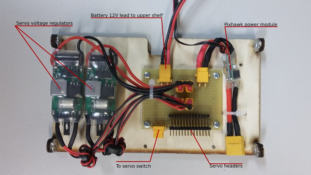
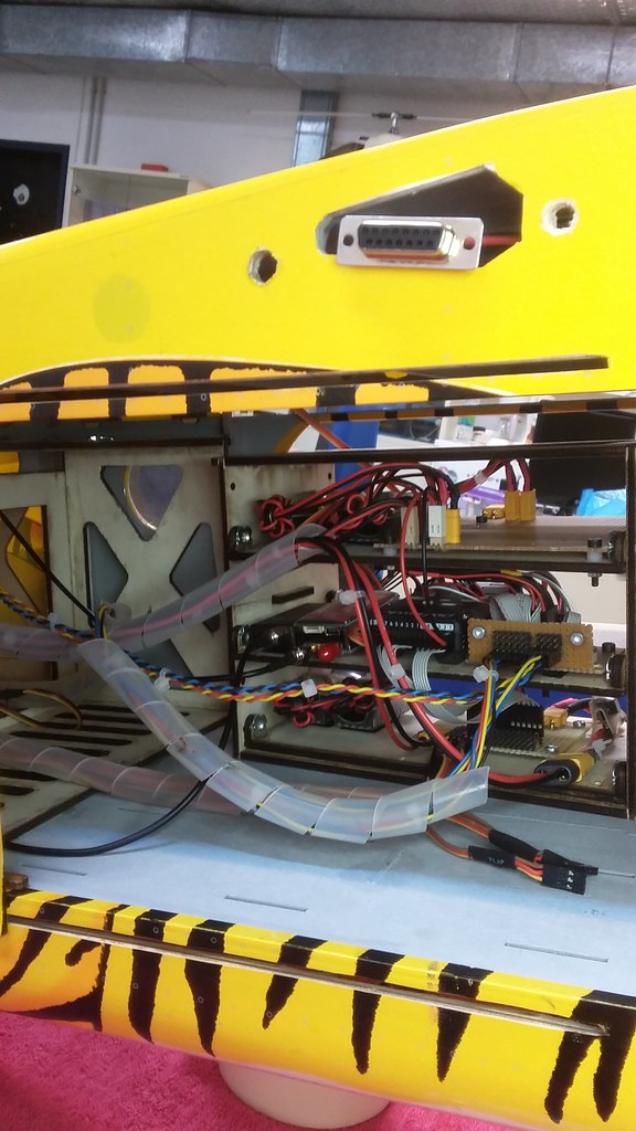
Okay, so let’s move onto populating each shelf. The bottom one hosts the Pixhawk power module, the redundant servo rail power supplies (see previous article) and the distribution board for the servo signals. XT30 connectors were used extensively, since technically the classic DuPond connector can’t handle more than 1A continuous.
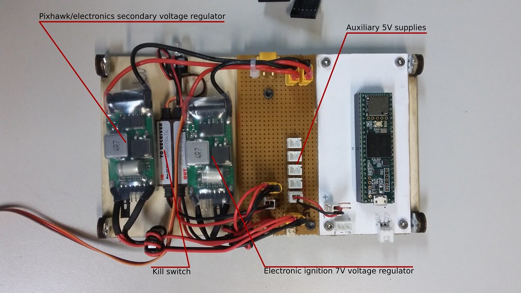
On the top shelf you can see the BEC powering the electronic ignition, the kill switch and the BEC for the secondary Pixhawk voltage supply.
A general purpose 5V rail for various electronics (mainly used for things mounted on the wings) has a central position.
The random Teensy 3.5 isn’t part of this article: it has been used to convert some digital measurements onto analog voltage to be fed to the Pihxawk’s ADC and is now deprecated.
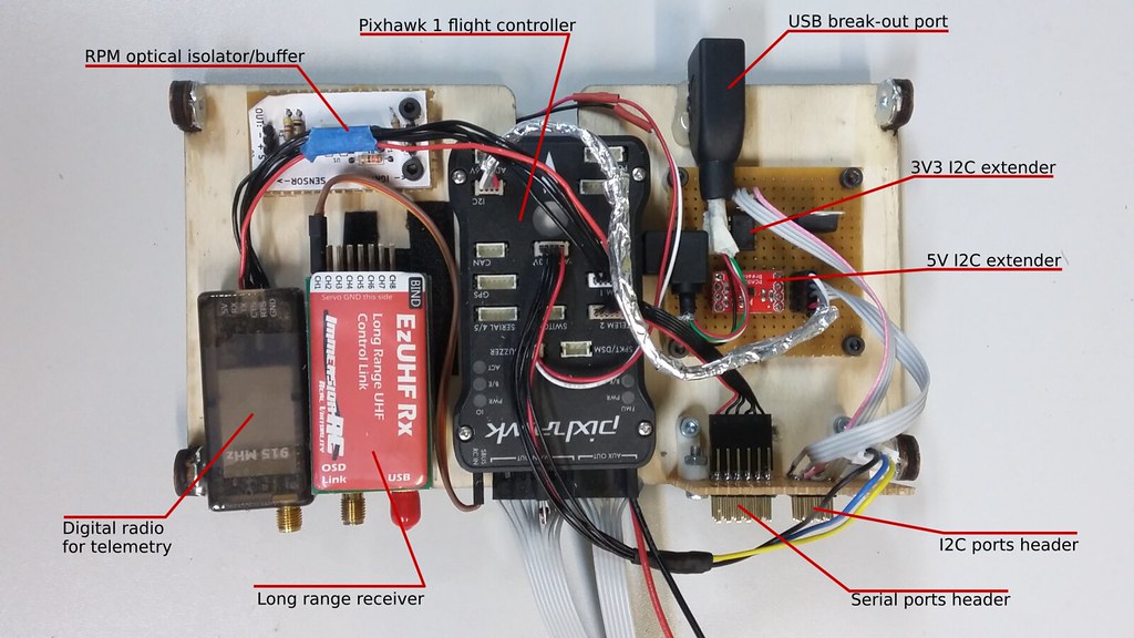
The middle shelf is were the real deal is: The Pixhawk 1 has a central position, to allow for as close an alignment with the longitudinal axis as possible.
The PPM input is connected to the LRS receiver (ezUHF brand). However, the kill switch signal (channel 2) goes directly from the receiver to the kill switch. We didn’t want the Pixhawk to have any say on the status of the ignition.
The telemetry radio is normally connected, nothing fancy here.
A USB extension chord has been permanently mounted on the board, to allow for easy access to Pixhawk’s USB port. Inserting a USB cable to pull the DataFlash log while the electronics are stored in place on the field is extremely hard. This solution makes the process a lot easier.
On the top left you can see a board with with paperscreen. It is an optically isolated RPM signal buffer which feeds readings to the Pixhawk and will be covered in a future article.
To the right, you can see the I2C and Serial ports broken out to standard 0.1" pin headers, for ease of access. The Serial ports are directly passed through, but some I2C headers are pre-buffered with range extending ICs, some with 5V logic and some with 3V3. More on these on a future article as well.
Wiring
External connections to the rack have been implemented in a number of ways.
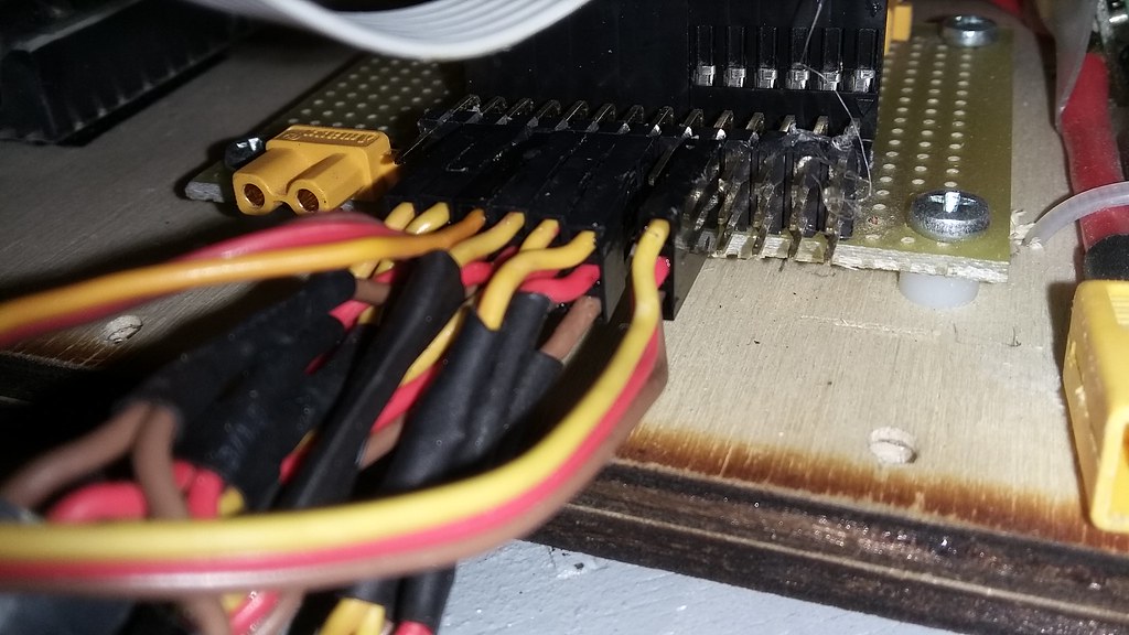
All servo cables were routed to a single point behind the servo header array. Traditional 0.1" pin headers were used, secured with hot glue.
XT60 and XT30 connectors were used for high-amperage situations, without any further securing.
RF connections are done with SMA connectors, secured with hot glue. We have found that they severely degrade with time, becoming too loose for comfort.
Small signal applications, such as the RPM, are using 0.1" pin headers, which may or may not be glued down, depending on the situation.
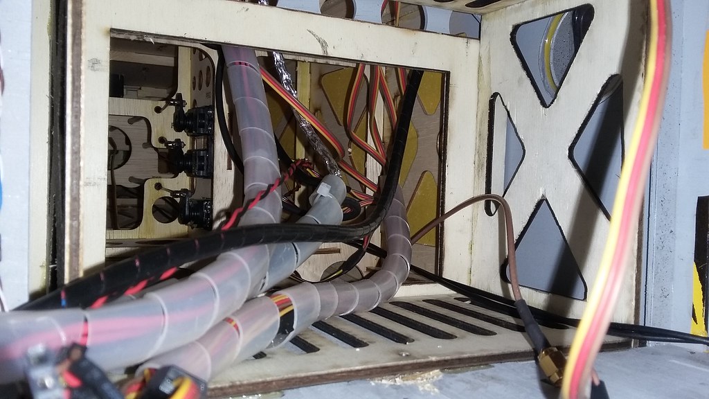
Most cable groups were wrapped with plastic spiral for logical clarity and neat packing.
Cables going to the back of the fuselage were not an issue in routing. The wings and front section were a bit more tricky, though. We needed to be able to unscrew and pull the rack forward and to the side, for access to the back connectors. Also, we didn’t want any connectors on the front of the rack. Keeping all the connectors to one side has the advantage that you can remove any shelf separately from the rest by unplugging its cables.
Those two specifications combined result in all the cables being routed to the back of the rack.
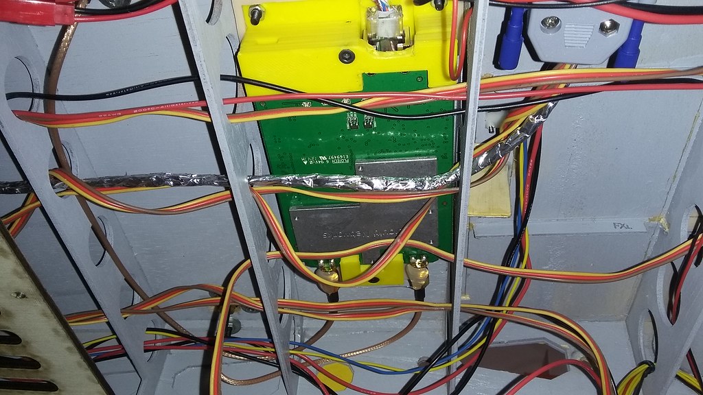
As a result, any cables going to the front of the fuselage and the wings were routed behind the rack, upward to the ceiling and over the rack. Thankfully, the Porter has nice circular channels on its ceiling.
Also, in order to be able to pull the rack to the front and side, we needed to allow for enough cable overhead length.
This approach worked wonders for us. The electronics are easily accessible, monitorable, stable, securely packed and modular. There was one significant downside with it, though.
The selected installation location was quite far behind the center of lift. Considering all of the structural parts, cables and components weight a significant amount, it isn’t surprising that we needed a lot of ballast to balance out the plane.
This has become a problem for us, especially during the last flight where extra payload was carried: the airframe was clearly at the limits of its loading capabilities. It would require more power, have less top speed and it would land too hot.
To improve this situation, we are currently migrating all the power supplies in front of the fuel tank, on the front section of the fuselage. We hope that this will save us up to a kilogram of weight.
This concludes this part of the UnATRaP blog series. If you have comments or recommendations, please let me know. Until next time!
Previous article: Part 8: Power Systems
