A recurring theme during the design of the UnATRaP UAV is the “we don’t crash” moto. In other words, we do whatever is necessary to avoid terminal failures, within reason.
The first link in a UAS chain is arguably its power system. The corresponding requirements were:
- Redundant power supply for the autopilot and its peripherals
- Separate redundant power supply for the servos
- Separate power supply for the electronic ignition system
The power system solution should provide for the above subsystems for at least one flight.
Payload power supply amenities were taken into consideration, but since specifics were uncertain, we opted to task any payload with bringing its own batteries.
A simplified overall schematic can be seen below. You can refer to it for the next sections of this article
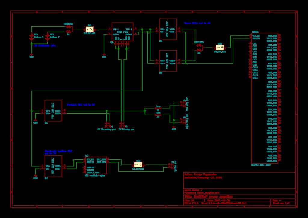
power_supplies.pdf (50.5 KB)
Batteries
Starting from the batteries, there was no reason not to go for the simple solution of 3S LiPo. However, we didn’t want an avionics battery to be a single-point of failure for the whole system. For that reason, we put two in parallel, with a diode bridge between them.
We didn’t mere join them in parallel, because in the case where one battery shorting internally, it would take the other battery with it. What is more, with the additional power of the second battery over a short-circuit, the risk of fire would increase.
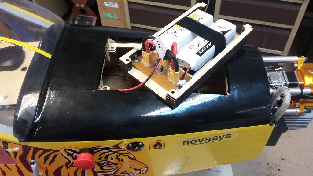
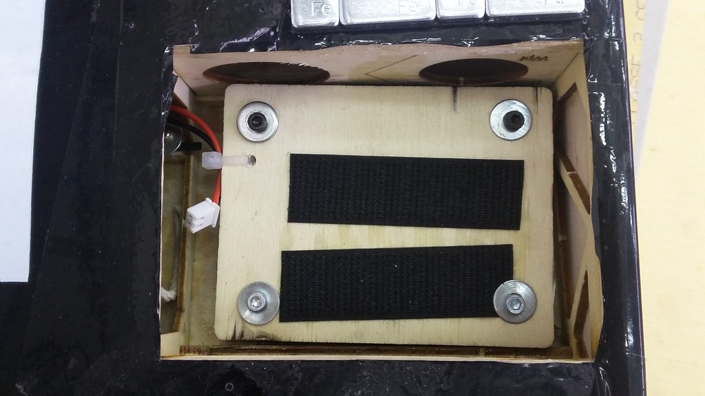
The MBR1545CT IC was selected for bridging the two batteries, and the whole assembly was mounted in a custom mount over the cowl hatch.
Another benefit of having a diode bridge is that both batteries are discharged at exactly the same voltage, down to 0.01V. Finally, with this configuration, batteries of different capacitance can be used without issues.
C-rating was not a concern for the batteries. We never expected to draw more than a few amperes in all normal flight conditions. On the other hand, we weren’t sure about the required capacitance, since we didn’t have accurate consumption numbers for the servo motors. We went for the trusty 2x2200mAh configuration and hoped for the best.
In the end, it turned out that 4400mAh were plenty for the whole flight day, leaving the batteries at about 11.2V.
Since the batteries currently help with balancing the aircraft we don’t plan to remove them, but if weight reduction is needed in the future, they are a valid target.
An extra XT60 connector was inserted, to allow for external voltage supply when the aircraft sits on the lab bench, but requires the batteries to be removed.
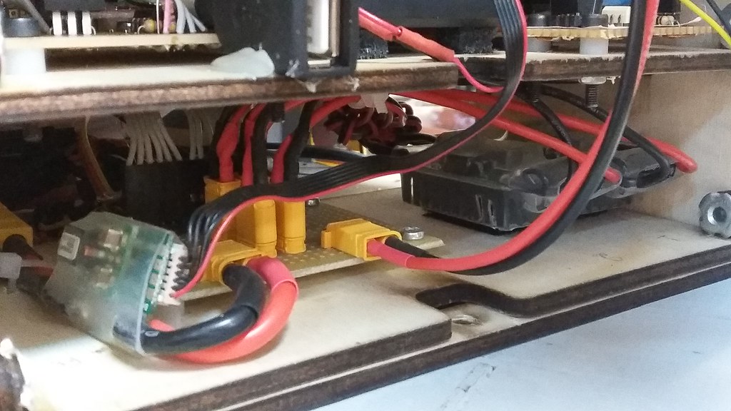
The battery and the relevant electronics board were mounted under the front of the fuselage, at the location of the original battery tray. However, a custom battery tray was designed and laser cut to fit in its place.

Autopilot Power Supply
Now that we had a good battery source, we moved into selecting the voltage regulators. We went for the overkill solution of YEP 20A BECs.
But before that, since we wanted to monitor the current draw from the aircraft battery pack, we installed the standard Pixhawk 1 power module right after the batteries. Since we did that, it seemed silly not to use it to power the Pixhawk as well, as a primary power source.
A YEP 20A BEC (we had a lot of spares) set to 5V was used, powering the Pixhawk 1 servo rail, acting as voltage source backup in case the Power Module died.
It is evident that the design had as primary goal to keep the Autopilot alive at all costs, so that it will at least act as a black box in case of a crash.
Servo Power Supply
The servos also have redundant power supply, in the form of 2 BECs set to 6V, joined with a MBR1545CT diode bridge, powering all servos. Also UnATRaP has 2 aileron servos and 2 (split) elevator servos, so we expect that some minimum manoeuvrability in the case of a single servo failure is guaranteed.
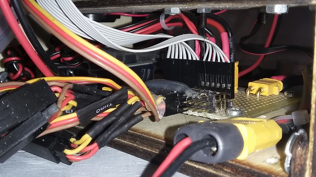
A power distribution board and pin header was made to mix the Pixhawk signals with the servo voltage.
We are using Hitec HS-5496M servos which come with 24AWG wire. We know that in theory this wire isn’t thick enough to handle the peak current of these servos, but since the manufacturer uses it, we played along and installed it for the whole span of the wing.
Electronic Ignition Power Supply
Just 1 BEC set to 7V this time. The ignition system is a single point of failure string, but we admit the chance to land dead-stick.
Power for external loads
Finally, we decided to provide a 5V power supply to small external loads, such as cameras and miscellaneous ICs, using the Autopilot’s secondary power source which has plenty of current overhead and clean voltage. This 5V rail was routed to the wings, were hardpoints can accommodate such loads. Still, just to be sure that no unpleasant surprises would happen in case an external load misbehaved, we decided to place 2A fuses in each wing voltage rail.
Power Switches
It is important to have manual control over the significant voltage sources in any prototype. When you need to quickly disengage battery power, you definitely don’t want to have to remove screws and mess with stiff plugs. Switches are your friends.
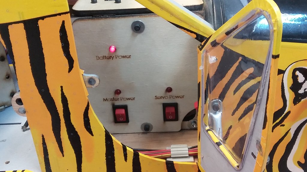
We used standard panel switches to control the autopilot and servo voltage lines. Be careful as you will have a hard time finding similar switches rated for more than 10A. This means that a different approach or an expensive switch is required for switching motor currents. Thankfully, we don’t an electric motor onboard.
Indicator LEDs also make your life much more sane.
A word of caution: Most ignition kill switches have a low-side switch, because that’s the easy thing to do. This is not up-to our standards, because if you somehow provide an alternative ground path from your engine chassis or ignition cables to your batteries, the ignition WILL TURN ON, despite of the switch status.
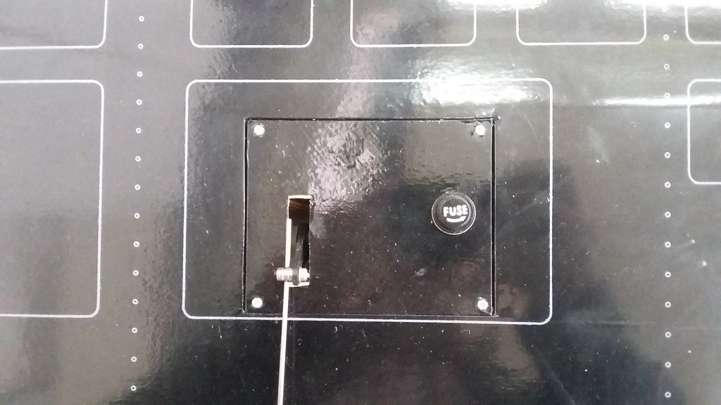
For that reason, we added a mechanical industrial-grade kill switch, visible on the first image.
This is also used as a no-brainer system for killing the engine in cases of emergency.
This is the current state of the power supply solution for the UnATRaP. In the near future we plan to migrate all the power electronics under the battery compartment to the front of the fuselage; The airframe has become too heavy/loaded and any weight placed behind the center of lift requires a lot of additional ballast.
This concludes this part of the UnATRaP blog series. If you have comments or recommendations, please let me know. Until next time!
Previous article: Part 7: Main Landing Gear
Next article: Part 9: Electronics Bay and Wiring