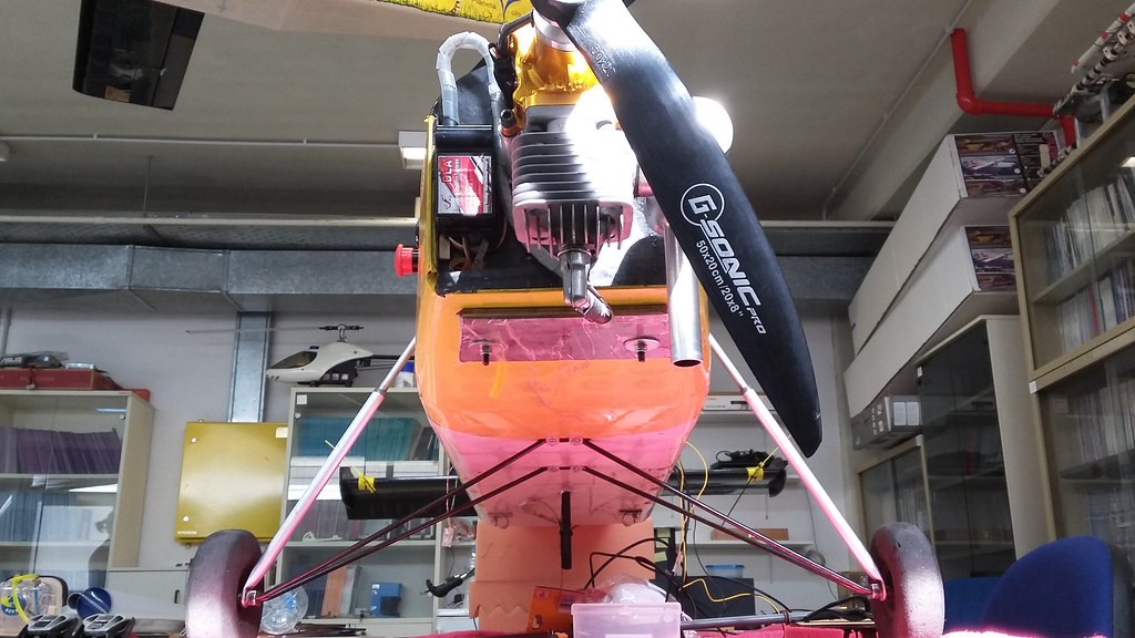
We have seen before that a lot of mechanical modifications on the basic Porter platform were needed, to support the added instrumentation weight and increased robustness demands. The main landing gear is no different.
The stock setup
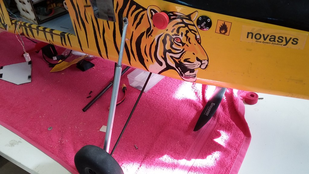
There is nothing really fancy here. For each wheel, a spring provides some damping for landing and two rigid rods, fixed on the underbelly, work as a suspension fork, holding the wheel in place.
The upper part of the spring is fixed on the side of the fuselage, while the rods are held down with plastic sheets and wood screws.
Reinforcing the mounting points
We knew, based on other people’s testimonials, that the mounting point of the spring on the fuselage was very weak. In hard landings, it is likely that the vertical fuselage wall will weaken, crack and subside.
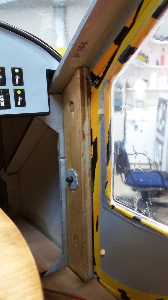
So, we went ahead and placed a 4mm plywood pillar on the inside of the fuselage wall, covered with 2-part epoxy. Other people have opted to add a “roll bar” between the mounting points, but that would interfere with the fuel tank installation. At any rate, as we will see below, our solution has worked fine under test.
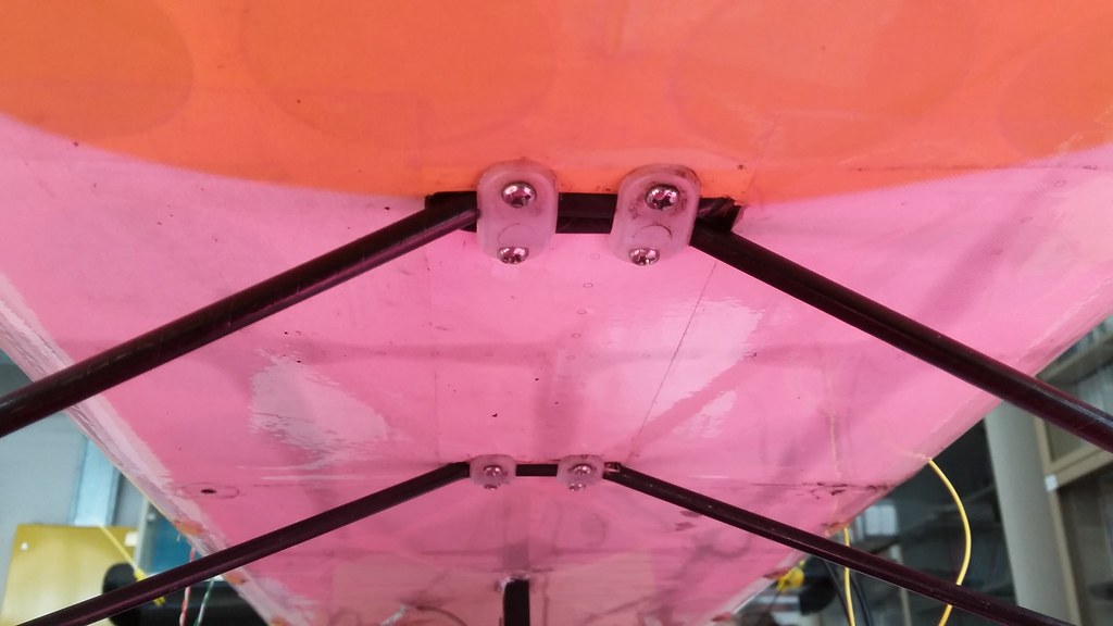
As for the rods, we limited ourselves to pouring some 2-part epoxy inside the accepting slots. The idea was to create a mating surface which would carry some side loads, and relief the plastic sheets.
Is it enough?
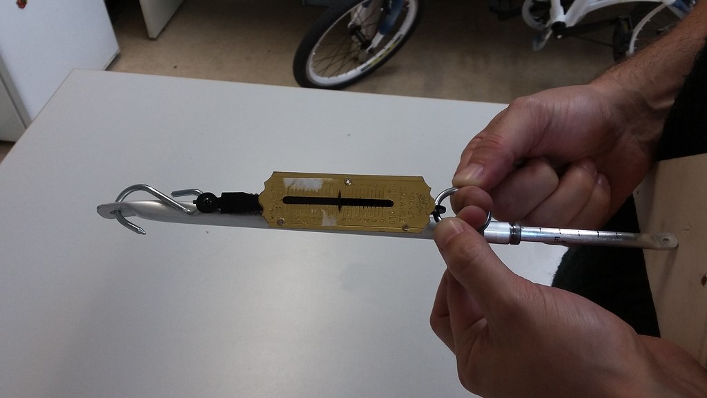
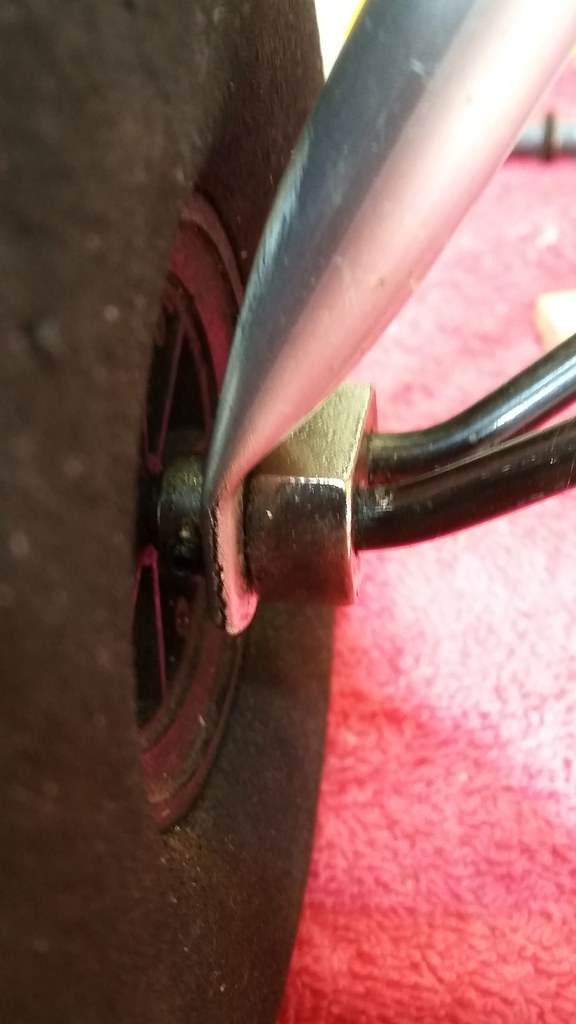
One should understand that these springs are designed for the stock Porter, which is supposed to weigh around 8kg. In fact, we can measure the spring constant. We used a force sensor to compress the spring by a fixed force amount and measured the compression length of the spring (see next figure). This gave us a constant of about K~2000 N/m. We can extrapolate this, notice that the spring has a maximum deviation of 7cm and estimate the maximum load at about 140N per spring.

Now, what would happen with our fully loaded UnATRaP platform, weighing around 12kg on a rough landing?
Here are the G-loads reported from Pixhawk’s IMU during a few select landings.
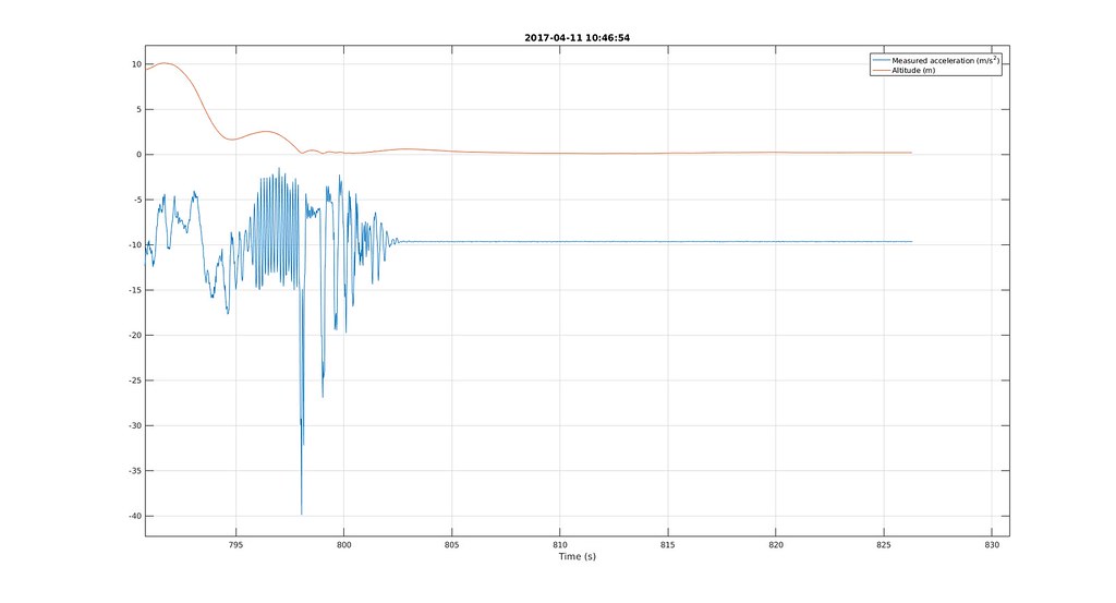
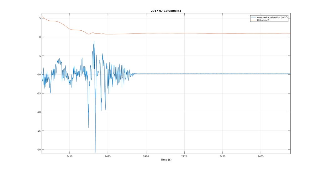
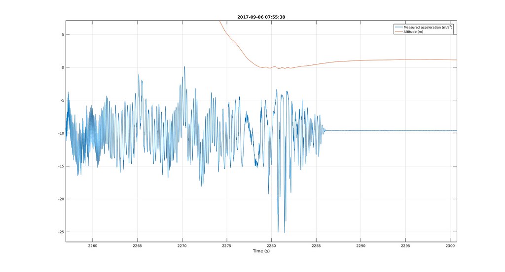
Based on these numbers each spring should be subject to about (300-470) N of force. That should max them out, right?
Right. Every time.


What is more, after 4 flight days, the aluminium damper has started to crack at its folds.
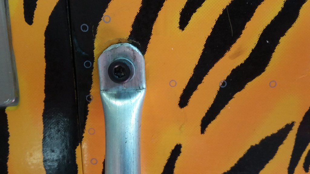
It is obvious that we should invest in replacing the stock dampers with some aftermarket shock springs or a different custom solutions quite soon. We are in the process of market research for suitable options, sadly without any serious results yet.
This concludes this part of the UnATRaP blog series. If you have comments or recommendations, please let me know. Until next time!
Previous article: Part 6: Wing Struts
Next article: Part 8: Power Systems