Hello.
I am having trouble setting the baud rate, throttle ID, and node ID to connect X11Plus with DroneCAN. Hobbywing DroneCAN ESC — Copter documentation common-hobbywing-dronecan-esc
I follow this page and use the DroneCAN Gui to make the settings, but they are not reflected.
In the Mission planner motor test screen I can rotate the motors. (with the bitrate reduced to 500000.)
What can I do to fix this problem?
Maybe this user can help.
Thanks for the answer, Jai.GAY.
The link was the first thing I looked at, but I didn’t understand what it had to do with this issue.
When I made this connection, I asked the Hobbywing tech a question and he gave me the Ardupilot connection page, but he didn’t say that I needed to give +5V.
If there is a problem with the power line, the tech should have advised me and I think the Ardupilot page should be corrected.
The motor I connected this time had an ID of 2 for some reason.
There are so many things in this world that don’t follow the manual.

probably the FCU has the same architecture as the Cubepilot and confusion over many years of legacy thingy.
Thanks for the response.
Please point out if I have misunderstood.
■About the CAN power line
I guess the bottom line is that there is a problem with the CAN power line and it won’t work correctly unless it is powered.
I know the servo power line is not powered, but the CAN is.
And like the servo, I believe it will work without +5V as long as the signal line is there.
■The equipment works without power to the CAN.
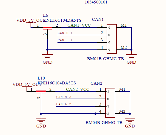
For reference, here is an excerpt from the CUAV schematic and a picture of it actually working with only a USB power feed with another device connected to the CAN port.
As you can see from the screenshot I posted above, the device actually transfers data even without the +5V power supply.
Am I missing something here?

Yes, I think this part is correct. Do you think there is a voltage level sensitivity issue? One rangefinder manufacturer insists that we use an external power source to connect to the Lidar sensor because the voltage is below what the lidar sensor is expecting.
Isn’t it a servo motor that comes with 3 wires? For the ESC, it needs external power.
So, are there some limitations of requirements and expectations of external devices?
as you said in your first post that the motor test from misson planner via FC to ESC is working so it couldn’t be an electrical / power problem. This test is also using CAN-Bus from FC to ESC.
You said that this test is running with Baudrate 500.000, so FC CAN_P1_BITRATE was set to 500.000 and FC was rebooted?
During setting of parameters which CAN_P1_BITRATE you are using?
Describe step by step what you are doing and what happens as result.
Thanks for the response.
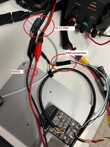
I think it would have been faster to show the actual wiring first. Sorry about that.
The X11Plus is an ESC+Motor integrated unit, and the only wiring to connect is the positive and negative poles for power, PWM (signal, ground) for signal, and CAN (CAN-H, CAN-L, ground) for signal.
I think the power supply for ESC operation is made internally using the one for power.
Juergen-Fahlbusch, thanks for your response.
Of course I changed CAN_P1_BITRATE to 500,000 and even rebooted.
Here is what I am trying to do
- set up the CAN settings in FC. Follow the instructions.
- reboot FC.
- motor test to make sure motors are working.
- Use the CAN gui tool to change the bit rate to 1,000,000, node ID to 1, and throttle ID to 1.
5.Change the CAN bit rate of FC to 1,000,000.
6.Confirm that the motor works by motor test.
I am having trouble doing 4 of this process.
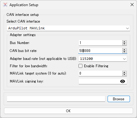
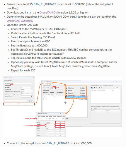
I am attaching a screenshot of the steps I am seeing and the motor test I did for reference.
It is DroneCAN so you can see that I am able to use ESC telemetry.
I am sorry but I don’t have your equipment so I am not able to simulate your steps I only can follow all information you write. So be as detailed as possible.
Did you run step 5 and step 6?
So did the motortest of step 6 worked?
Is your screenshot the motortest of step 3 or step 6?
Also the picture of the flow is nice but this only out of the known documentation.
During step 4 it is more interesting what are the results before and after the single steps you did.
Are you able to do step 4 again?
The yellow wire is ground wire, the gray wire is CAN-High (CH), and the green wire is CAN-Low (CL).
The optional serial communication power system. Yellow, red and green cables are the data output and upgrade signal line (the ESC system is upgradable).
The black and white is the PWM throttle wire, the black wire is ground wire, and the white wire is signal wire.
You may not having CAN-bus version.
Thanks for your concern.
I have contacted Hobby wing support to get an answer regarding the CAN connection.
Then Hobbywing support should guide you on why you have this issue.
Yes, that’s right.
Thank you for taking the time to go along with my question.
Ok, now we get the confirmation that your ESC is a CAN Version. But this was already clear before as you wrote that you can run motortest with CAN baudrate setting 500.000. Am I right?
So, what are the answers to my last post? Maybe we can alltogether more detailed figure out on what point is something going wrong.
Of course.
Here is my procedure.
When I press the “SET” button on the third screen in the image, I don’t know what will happen, so I don’t know what the right answer is.
All I know is that it does not connect at 1,000,000.
I have also confirmed that even if I select 1,000,000 on the first screen of image 1, I can still operate image 2 and image 3.
I have changed the ID to 4 for clarity since I received DATALINK v2 at hand.
Now, what is wrong?

I think you read. do you think sequence issue? I still feel that Hobbywing wrote the DroneCAN Gui Tool and make the X11 plus motor, only they can better support you.
- Disconnect any other DroneCAN devices from the autopilot’s CAN1 port
- Connect to the autopilot and set CAN_P1_BITRATE to 500,000
- Reboot the autopilot
- Power on the ESCs, they should stop beeping
- Use Mission Planner’s Setup, Optional Hardware, Motor Test page’s “Test All Motors” and all motors should spin
Next correct the configuration of each ESC (I am not sure, maybe you have to connect one by one):
…
Set ThrottleID and NodeID to the ESC number. This ESC number corresponds to the autopilot’s servo/PWM output port number
…
Yes.
As you can see in the connection photo I posted the other day, the devices connected to the flight controller are a serial-connected GPS/compass and one motor connected to CAN1.
The reason I set ThrottleID and NodeID to 4 is to make it easier to see if the settings work when they are set to 1 respectively.
I have yet to have a case where it worked.
All I can do at this point is change the motor ID and connect to CAN at 500Kbps.
I can’t even fly the drone because I don’t know if it is safe to communicate with 6 motors at 500Kbps.
You can try it WITHOUT the propeller mounted to hear the motor feedback spin “sound” at various throttle stick levels first. If you have an RPM reader/decoder, it will be best to verify all the motors. If okay, I think you should be able to perform the first flight.
I am very sure you cannot mix 1Mbps and 500Kbps devices on the same CAN port, so double-check that.
So I understood
- now that ou are able to change Throttle ID and Note ID
- but not the Baudrate
- you can operate aslong as the FC CAN baudrate setting is 500.000 Baud
One maybe stupid question
As this ESC comes per default with 500.000 Baud, is it even possible to work with a higher baud rate. The manual is not given any information about this


