I have a quad with very rigid G10 arms and a not so rigid frame. I’m using a very compliant mount with a light weight PixRacer FC and I have this vibe problem. Not to the 60 range but I can’t really get it better than ~30Z. I tried weights and a foam damper between the mount plates (foam helped) but in general I have just tuned around it with the filters and lived with it. Occasional clipping but if performs generally good. Using Dynamic FFT based notch.
So you believe in your case the issue derives from the flexible frame. I actually tried to add a reinforcement plate to my top plate but with dubious if any results. I have really run out of ideas at this point…
I think so. The battery is below the lower plate so not offering any mass to the upper plate where the FC is. I was thinking about trying to couple them but for what this craft is for, just fun flying and experimentation, it’s OK.
I see… unfortunately this copter is being used for long range missions and delivering packages, so I can’t really have anything not working very well. I just opened a separate topic to see if someone has any other ideas.
In my experience the Pixracer is extremely susceptible to vibration, this is not just the vibration but something electrically to do with the gyros. It’s actually what got me started on the whole dynamic notch in the first place because I could not get a good tune or good enough vibration isolation with 3.6.
Hi, are those same motors and props on your Octo top/bottom mounts? That may be a contributing factor to vibrations if so, ideally lower motor should have higher kv and shorter props, like 16” 300kv top, 14” 470kv bottom.
The motors are the same but the props not. From what I have found out you want to somehow distribute the upper/lower load evenly so what I did is use a 16x5 prop on the top and a 15x6 on the bottom. I get pretty good efficiency that way. I don’t know how this would contribute to vibes. Only if the props were the same and the tip vertices were colliding
I just want to mention… I’ve had problems w/ vibrations in my microcopters. Vibes are under 5 on one of them, but I got “vibration compensation on” messages and other vibration related symptoms.
The frame is so small, I didn’t think arm flex would be an issue. But, last weekend I decided to try stiffening the arms. I glued carbon fiber rods under each arm. And… Issues are gone. Vibrations look the same in the logs. My FFT shows a frame resonance peak is gone, though. And like I said, most of the vibration issues I was having are gone on that copter. It still leans under throttle, which looks like a vibration issue, but not sure.
Anyway, sometimes the logs don’t show the full story, and frame flex is apparently a serious issue.
If an increased gap causes more vibration, I think the motor mount adapter is (heavily) overloaded. After suffering a lot from Z vibrations in the last years, this is what finally worked for me to mount a single motor (with 17inch prop) to the arms. Z vibes are usually between 1 and 5 .
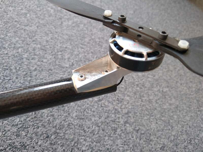
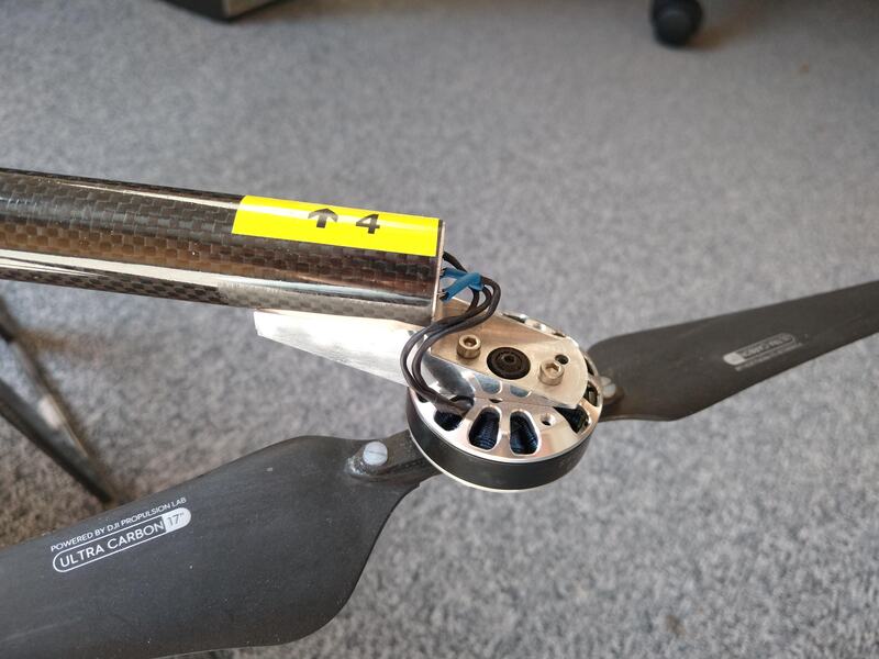
The aluminum part is CNC milled from bar stock, about 9g each. Unfortunately it takes more than three hours on the machine, four tool changes and milling from two sides for a set of 4, making them $$$ expensive.
The motor mount is glued and riveted to the boom. Inside the boom is a thin aluminum liner to further increase the stiffness of the joint and to protect the carbon tube from punctual loads of the rivet. The idea of having to mount two motors on each arm would be my worst nightmare, to be honest 
BTW, my current X4 design is far more reliable than my previous X8 designs ever were. Whenever a motor failed in the X8, at least a second one also did.
Firstly thank you for the detailed reply!
What do you mean by overloaded? Forces are too strong to handle them properly? Truth is the motor mounts are 3D printed (from nylon composite) which makes them pretty stiff but nothing comparable to aluminum.
Do you think the small amount of flex that they allow could be causing it?
I tried tying down the copter and spinning the props to see if there is any visible vibrations on the motor mount, but there was none and props seem to be tracking really well.
I kind of hope it isn’t the motor mounts since there is little I can change there, and I have no access to any CNC equipment…
As far as redundancy is concerned I have been able to complete a whole 4km mission with one motor out (part of a test), but yeah it’s likely to have a failure that involves the whole arm in which case there’s little you can do.
EDIT: Also what do you mean vibes 1-5, I assume not a result from the VIBE window of MP?
Yes, I think it just lacks stiffness. It is not about the small flex or deflection, it is about the periodic movement in both directions and especially the resonance points and beat frequencies between different motors/propellers. I previously built my motor mounts from flat carbon material, 2x 2mm, one on the upper side of the boom, one on the lower, with distance bolt between them at the top. Same story there - not stiff enough, high z vibes (again with one 17" drive).
BTW, almost more important than the motors mounts is the design of the center. With single arms, placed with clamps between two milled plates of carbon fiber I had no luck in heavier copters.
Regarding vibe measurements:
Yes, during stable hover outside of ground effect and in calm weather, my copter usually logs VIBE.z values between 1 and 2. While moving forward, no more than 5. Full power vertical climb is worst, around 7-9, but I never do that in reality. If the value is way beyond 10, something is mechanically wrong, I would better land in that case. The X and Y values usually are around 3-7, depending on the wear of the motor bearings and props.
I see. Maybe I can get some 2-3mm carbon plates and get them cut to shape for my motor mounts.
The values you mention are the bar graph values (with the 30 and 60 marks) or the clipping values on the right? Thanks again for your input:)
Yes, the bars - usually, there are no bars. If clipping is non-zero, the vehicle is IMHO unsafe to fly.
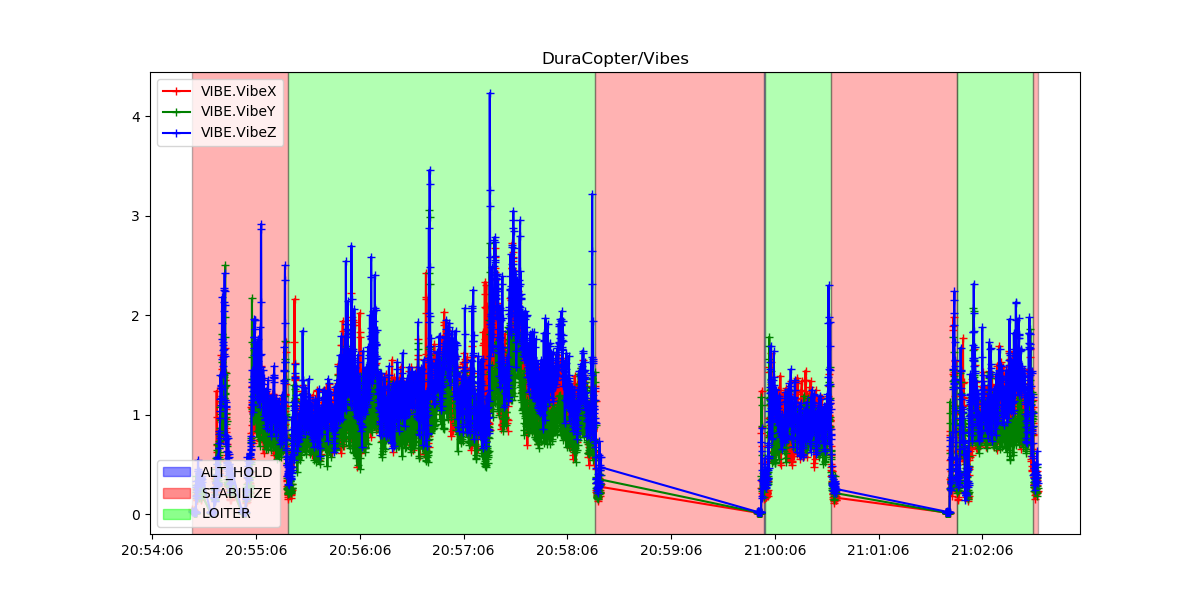
Here is a log of a short test hover in calm conditions, after changing all motor bearings and fine-balancing all props.
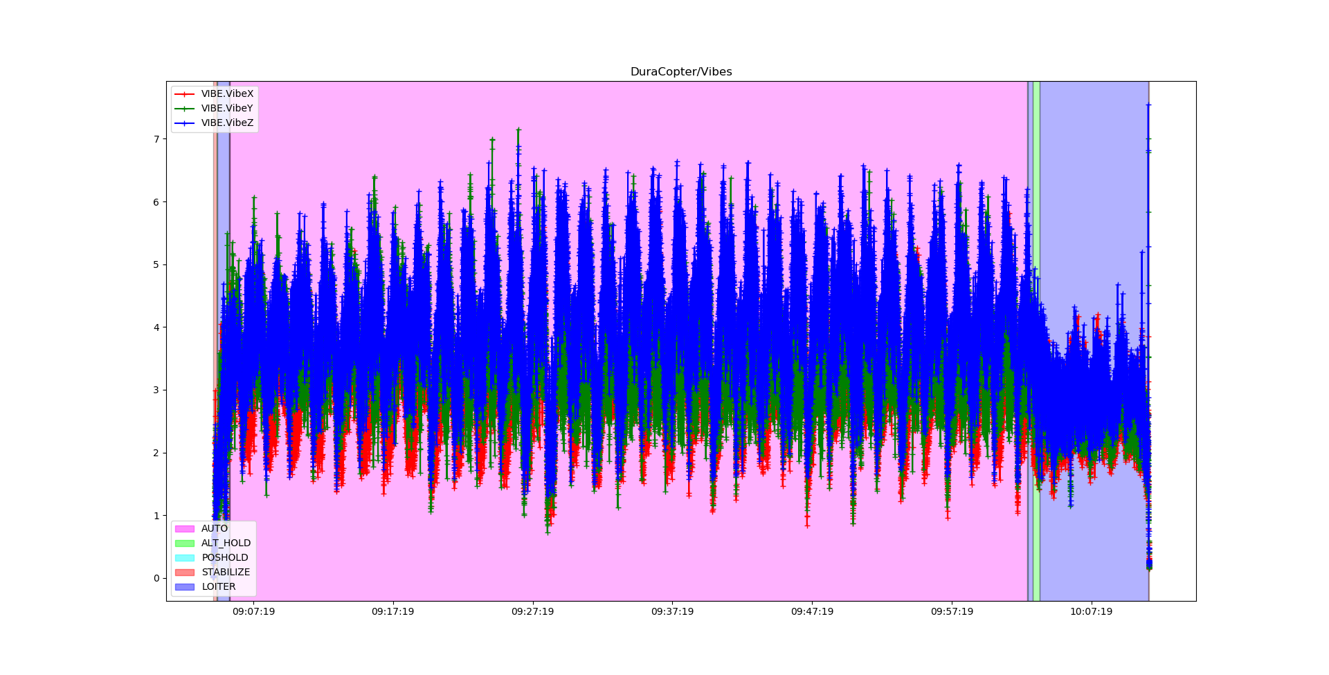
And this is a 100 hectares / 70 minutes photo mission at a ground speed of 10 m/s in 95m AGL on a pretty windy day with heavy thermals and gusting. You can nicely see the upwind and downwind legs in the vibe levels. At the end of the flight, there was some hovering for some bonus shots, as the battery wasn’t empty after the work was done
I’m now really impressed with your flight times ! 70 minutes of actual flying on a copter is quite the feat! I’d love to see some more info on the copter 
On another note I’m still battling those vibes… Last thing I am gonna try is make a solid 3mm brace for my upper plate and call it a day. I even printed some thicker motor mounts with less flex but no avail… Which kinda makes me wonder if the issue could be something else…
As a last ditch effort I may try swapping the pixhawk 1 for a cube. But I’d really rather get to the bottom of this issue (with my sanity intact that is…)
Hi Andy,
I am trying to read up the docs section about setting this notch filter on the planes - is it only supposed to be done using RPMs read-out, or can it also work same way as it is configured on copters? Essentially, can it be done using throttle input as a param for planes setup?
The code is in there to use throttle on plane. @Leonardthall did that code, I have not tested it myself - but it should work.
I have gone through the Harmonic tuning guide for my Quad and am pleased with the results. I can’t understand what I need to do for the Notch Frequency Scaling stage.
INS_HNTCH_ATT,15
INS_HNTCH_BW,47
INS_HNTCH_ENABLE,1
INS_HNTCH_FREQ,95
INS_HNTCH_HMNCS,3
INS_HNTCH_MODE,1
INS_HNTCH_REF,0.2554156
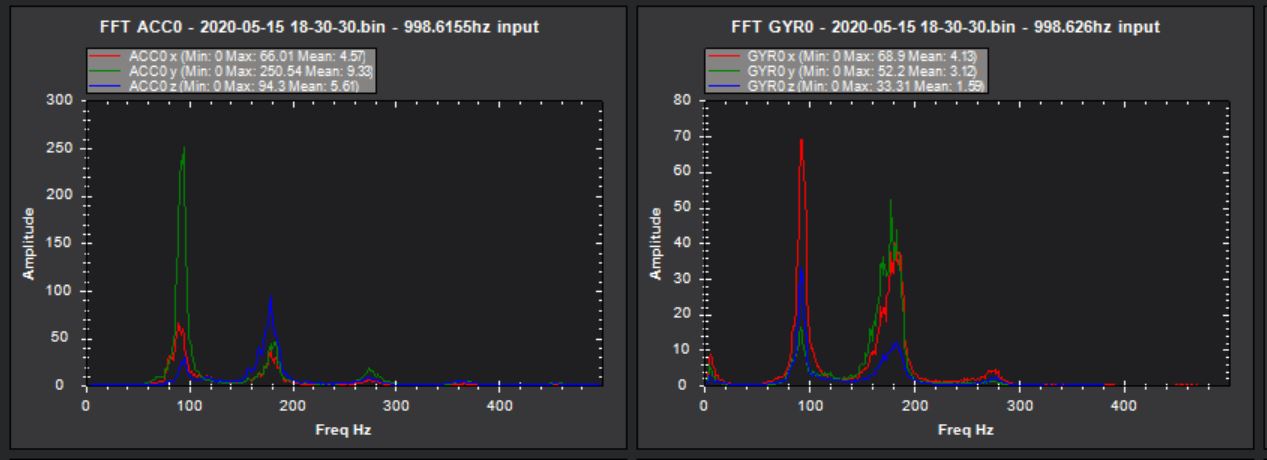
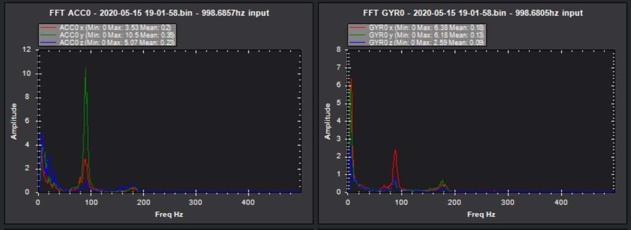
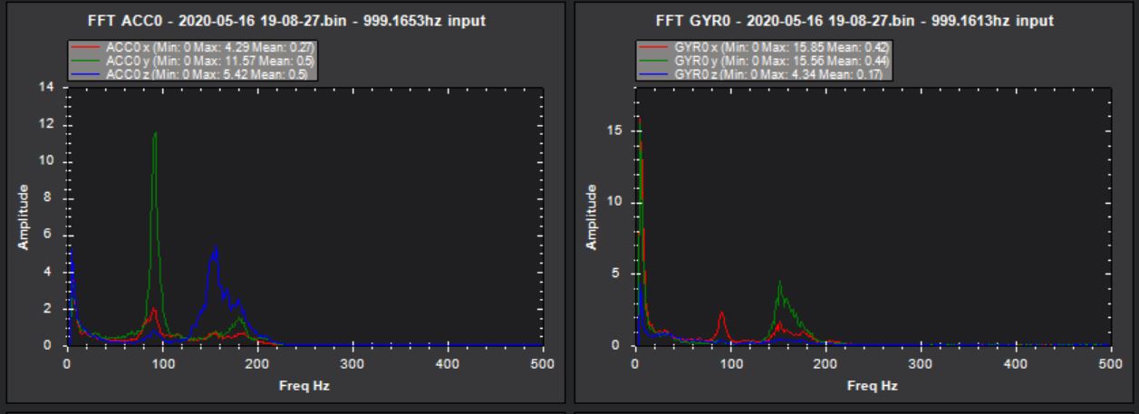
I have included the 3 test flight FFT plots
Baseline
After Filter
Dynamic Flight
Looks pretty good.
Increase INS_HNTCH_ATT to 40. More would definitely help, and 40 seems to be the default suggestion for it lately.
Frequency scaling… Basically look at the logs or guess the lowest frequency you want the notch to cover. Then enter it into the equation in the instructions. Then use the result as your parameter. It’s been a while since I’ve done it so I can’t give you better specifics at the moment. Someone else will probably answer. Otherwise I can reply later when I have more time to remind myself of the procedure.
I tend (I should say used to tend as I use FFT all the time now ) to look at both peaks to guess the correct notch frequency. Your upper peak looks more like 180Hz to me and I think the lower may therefore be closer to 90Hz. A @wicked1 says use ATT 40.
In my case to cal INS_HNTCH_REF
0.2554156 * SQUAREROOT( 90 / 180 ) = 0.1806061
I had thought 90Hz was my hovering frequncy??