I know that this question can be out of topic, but I’m very interested in understanding the math which is behind the calculation for the heading and the motor commands used by ArduPilot Rover. In particular, I’m very curious to understand how and if the Kalman filter is used when, for example, the compass is disabled and only two GPS modules are used to calculate the vehicle’s yaw.
I can’t give you the detailed computations involved, but effectively, accelerometer data is used to “fill the gaps” between GPS heading updates, and it does so fairly well, even when the updates are interrupted for several seconds at a time.
Thank you! So, when the compass is disabled, are the angular velocities and the accelerations from the IMU always considered together with the DUAL GPS for the heading?
I was thinking that only the GPS values were used for the heading calculation.
If this is correct, I could use my XSENS Mti-300 instead of the standard pixhawk IMU in order to improve the heading calculation with the DUAL GPS configuration. Am I right? (The Mti-300 is a very accurate sensor compared to the standard one used by pixhawk.)
Is there a Matlab code or some equations that explain how the heading is calculated or the used algorithm is proprietary and so we can only guess how it work?
I recently compiled on Ubuntu the Ardurover firmware, is it possible to find the equations there?
If I got it, the heading and the position is calculated without using the compass (I disabled the compass) and they only rely on accelerations and angular velocities from the IMU plus the coordinates coming from the two GPS modules.
I’m trying to import the imu and gps data in Matlab in order to reproduce the calculations because I’m interested in being able to test the data in a more convenient way and to plot some graphs.
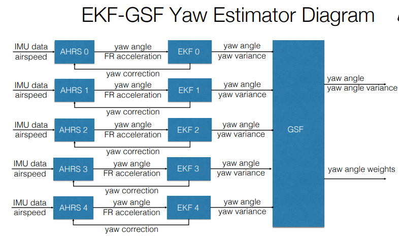
The article showed this explanation about the use of GSF:
So, five instances of EKF are run by using the same input coming from the IMU and then the GSF use their estimation to further calculate the yaw? If yes, how the GPS modules are handled?