That is a good question. I never saw the display with the dots myself.
1 Like
Im not seeing it in mission planner as a separate mavlink component.
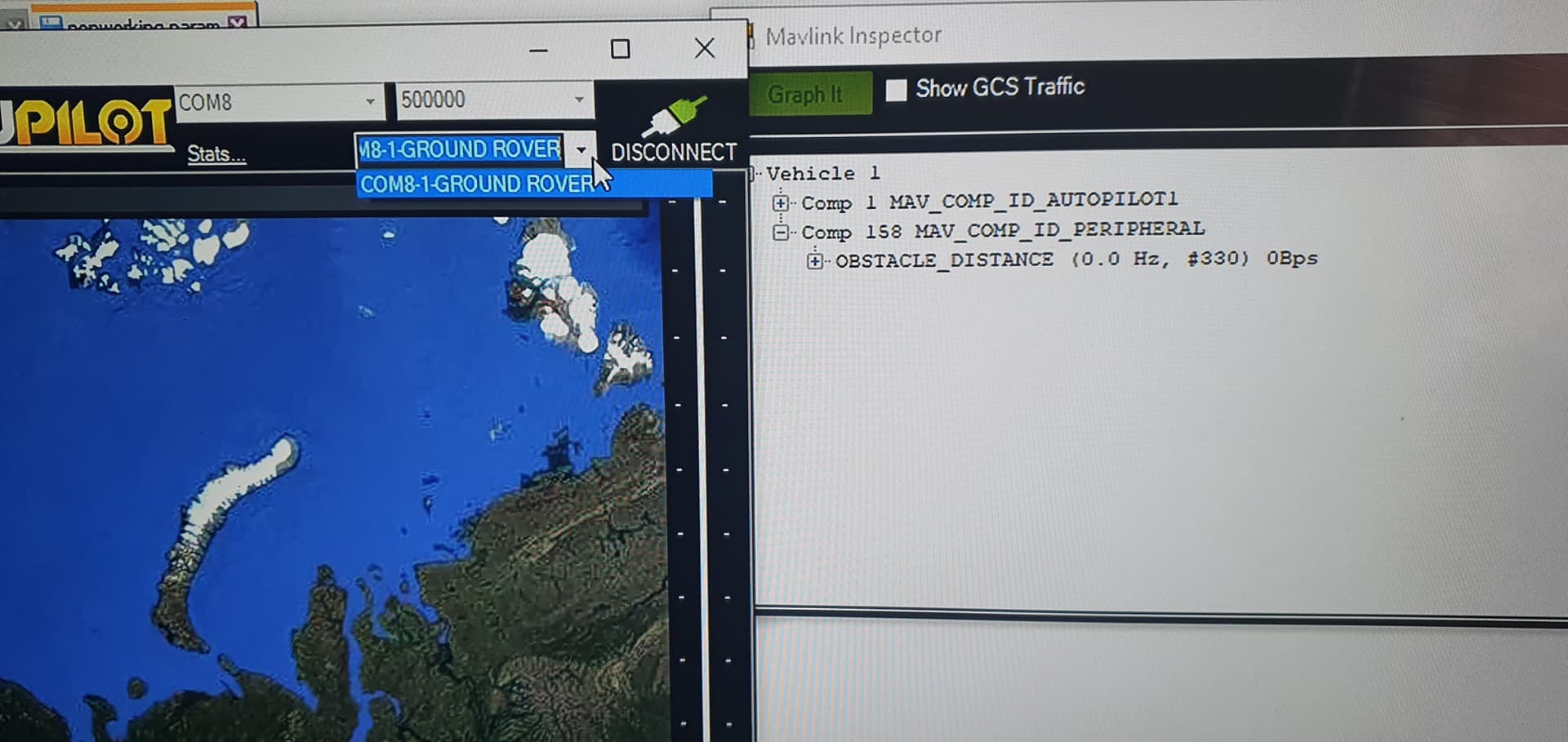
I think the problem is its not sending a heartbeat.
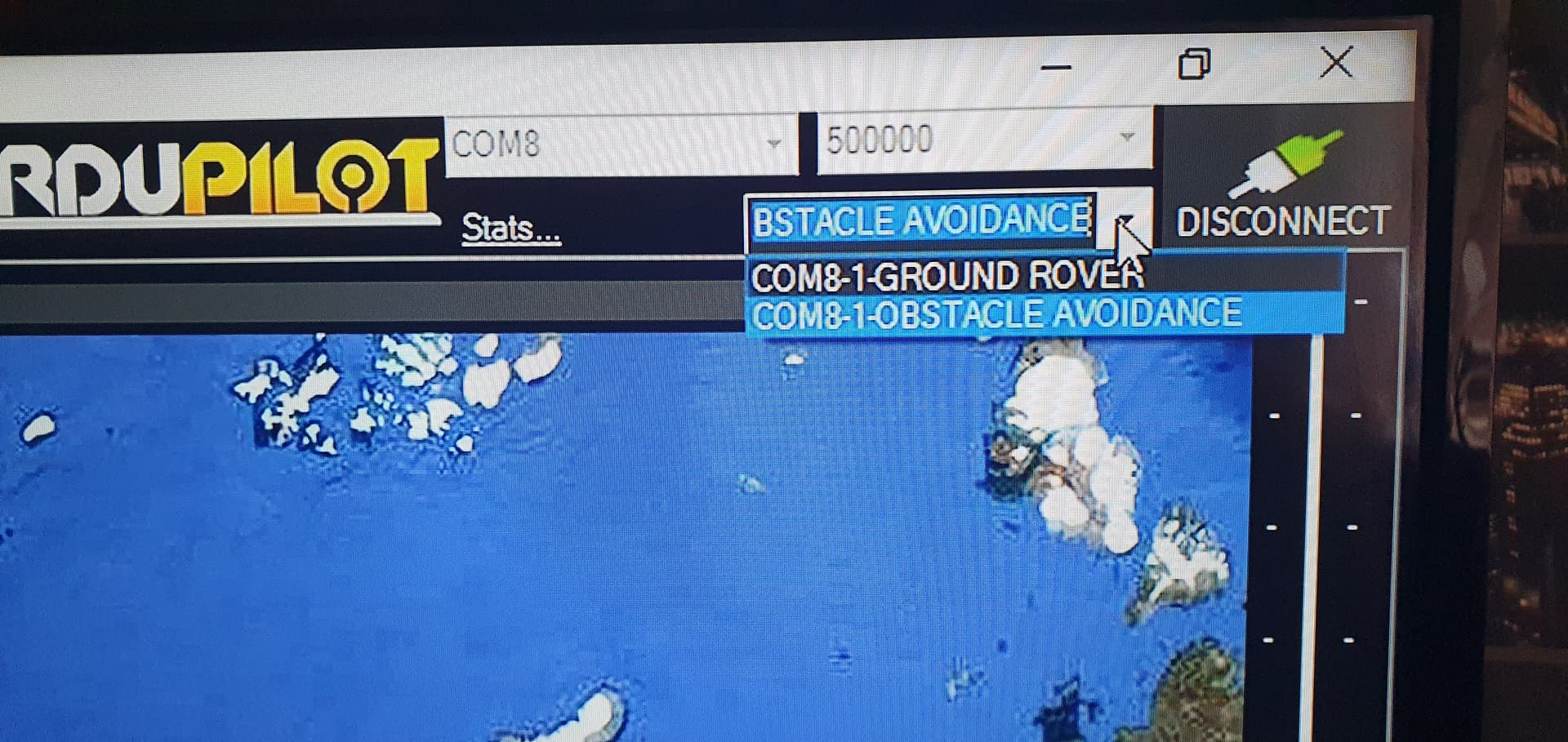
Got it working, It needs to broadcast a heatbeat then you can select that mavlink component in mission planner and you will get the high resolution view.
 int sysid = 1;
  //< The component sending the message.
  int compid = 196;
  uint64_t time_usec = 0; /*< Time since system boot*/
  uint8_t sensor_type = 0;
  distances[messageAngle/res] = Dist-2.0f; //UINT16_MAX gets updated with actual distance values
  uint8_t increment = 3;
  uint16_t min_distance = 30; /*< Minimum distance the sensor can measure in centimeters*/
  uint16_t max_distance = 500; /*< Maximum distance the sensor can measure in centimeters*/
  float increment_f = 0;
  float angle_offset = -FOV/2;
  uint8_t frame = 12;
  uint8_t system_type = MAV_TYPE_GENERIC;
  uint8_t autopilot_type = MAV_AUTOPILOT_INVALID;
  uint8_t system_mode = MAV_MODE_PREFLIGHT; ///< Booting up
  uint32_t custom_mode = 0;                 ///< Custom mode, can be defined by user/adopter
  uint8_t system_state = MAV_STATE_STANDBY; ///< System ready for flight

  // Initialize the required buffers
  mavlink_message_t msg;
  uint8_t buf[MAVLINK_MAX_PACKET_LEN];
 int type = MAV_TYPE_GROUND_ROVER;
  // Pack the message

 mavlink_msg_obstacle_distance_pack(sysid,compid,&msg,time_usec,sensor_type,distances,increment,min_distance,max_distance,increment_f,angle_offset,frame);
  uint16_t len = mavlink_msg_to_send_buffer(buf, &msg);
  Serial1.write(buf, len);

  // Pack the message
  //mavlink_msg_heartbeat_pack(sysid,compid, &msg, type, autopilot_type, system_mode, custom_mode, system_state);
  mavlink_msg_heartbeat_pack(1,196, &msg, type, autopilot_type, system_mode, custom_mode, system_state);

  // Copy the message to the send buffer
  len = mavlink_msg_to_send_buffer(buf, &msg);
  Serial1.write(buf, len);

}
```.
1 Like
Good find, I will try this with my lidar when I am back home.
1 Like
the sonar im using is really slow, il have a go later at using a vl53l1x.
Why do you keep all the poti stuff in your servo version? I guess analog read is slowing down the code quite a bit.
I keep it there so i can drive the servo using alternative inputs, i can tie it to something like the camera gimbal so it ranges where the camera points, or just manually control the scan using the rc. my sonar tops out around 10hz so 72 slices means im limited to around 1 scan every 7.2 seconds. accuracy is more important to me than raw speed. I have 5x fixed underwater sonars for close range detection.
I also have a radar im planning on adapting to this system for use above water.
What would be nice is to request data from the flight controller to alter the scan profile dynamically, so when the boat is under 1mph do a full 360 scan to cover all sides but reduce the scan field as speed increases so it would drop from 360, to 180, to 120, or even 60 degrees at full speed.
another idea would be to limit the left and right scan field as the boat rolls so its not scanning the surface of the water for false returns.
Does your setup really fill all 72 segments? With my lidar/stepper setup, the scan range is limited to 120° and the FOV of the lidar is ca. 3°. So I can fill 120 / 3 = 40 segments with distance data. I could overlap the scans a bit and the FOV of the lidar is actually 2.7°, if I remember correctly. But the small gaps do not really matter for a moving vehicle where the perspective for the sensor changes all the time.
Your sonar probably has a greater FOV and the servo does 180° max. So take the 180 / SensorFOV = number of segments. And if you use microseconds instead of degrees in the code, you can move the servo in smaller steps and even beyond 0/180 degrees, if your servos allows that.
myservo.writeMicroseconds(1500);
min 700
max 2300
Yes, false positives from the ground are quite annoying. If you drive on a sports field and place a few objects, it is all fine. But as soon as there are slopes, vegetation, curbs it goes all crazy.
I did see that it wasnt always filling every segment, took me a while to figure that out as i was still working out timing issues, I have increased the scan field to 180 degrees and set the resolution to 2 degrees to make sure it could fill them all for testing. The sonar does have a much wider fov when dealing with flat surfaces but when dealing with smaller objects at long range the detection range is much narrower so having fine slices is still useful.
I want to use it to look for fish as well as path planning.
Another idea was to mount it on a gimbal for tilt and roll to prevent ground detection, it doesnt have to be fast or high resolution so servos would work fine.
With 2 degree steps you get 90 values. If you use writeMicroseconds, you can get the 2.5 degrees you need.
the stops on the servo dont really matter its all about how many sections the pot is split into.
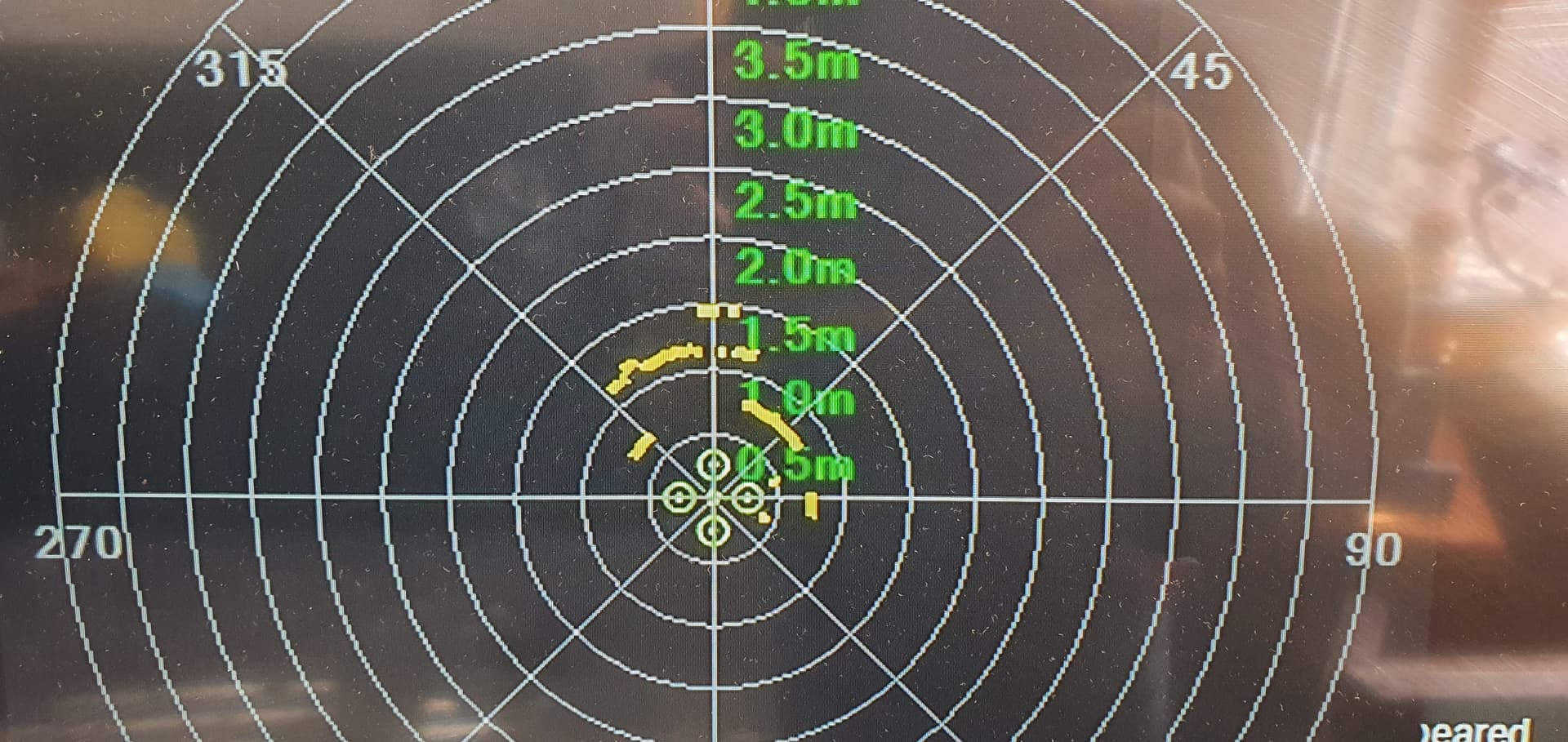
I changed the FOV to 360 and resolution to 5 degrees, then split the pot into 144 sections to get the math to line up. giving me 72 slices now all filled. The key was getting the end points bang on or it wont use all the slots.
I have 3d printed a 2:1 servo gearbox to turn my 180 servo into a 360 servo, if it works il either get a proper robot feedback servo or a 1.5 turn sail winch servo.
@count74 I was looking at the RP-lidar a1, its only 100 and i dont think it would take much to adapt your code to it using the provided example
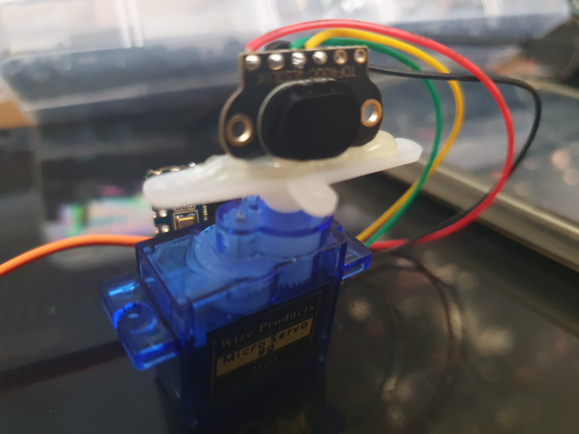
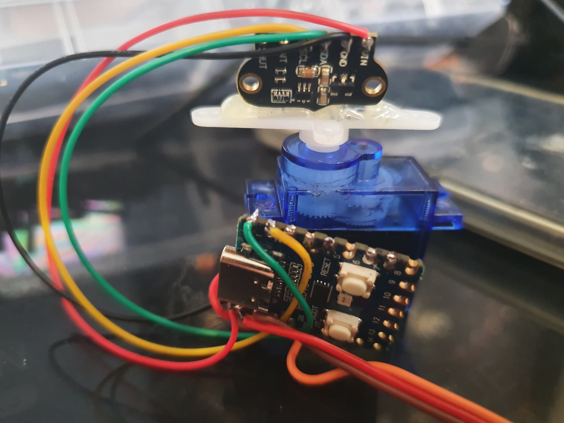
I am working on another version of this that is as small as possible. Its almost there just some tidying up to do.
Using a RP2040 controller, a 9g servo and a Vl53l1x lidar. Im just using the servo pwm to set the position rather than the analog feedback.
1 Like
I did that too before using a stepper motor. The servos I used were not happy at all about being operated constantly.
1 Like
I have burnt one out before testing a setup like this, running them too fast and not giving them time to stop at the end before the change direction really causes them to heat up fast.
there are some tiny stepper motors out there, I will look into adapting one.
this looks nice
https://www.printables.com/en/model/410798-lidar-scanner-head
@count74 @ppoirier do you have any examples of using the 3d mavlink input for a rangefinder? I want to make a solid state 3d version of this using the VL53L5X, its a 60 degree 8x8 array but i cant find anything for 3d mavlink its all python. That’s basically the point of this creation is to get the code and i2c working on the RP2040 then I’m going to make a 2d version first by just using one line of the array. first before attempting 3d. i could make the line of the array selectable by the angle of the vehicle since it’s already connected to mavlink, or just make it scan each line.
how would multiple mavlink rangefinders work, does it just order them based on port?