Talon vtol 4+1 type h

Hello:
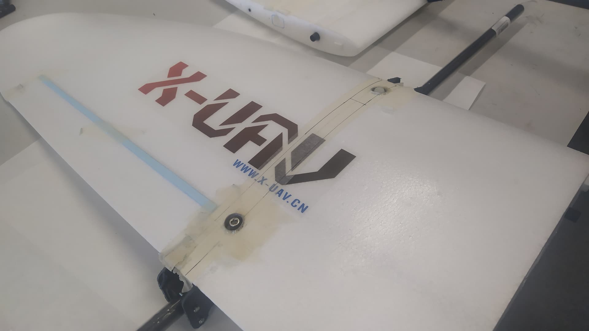
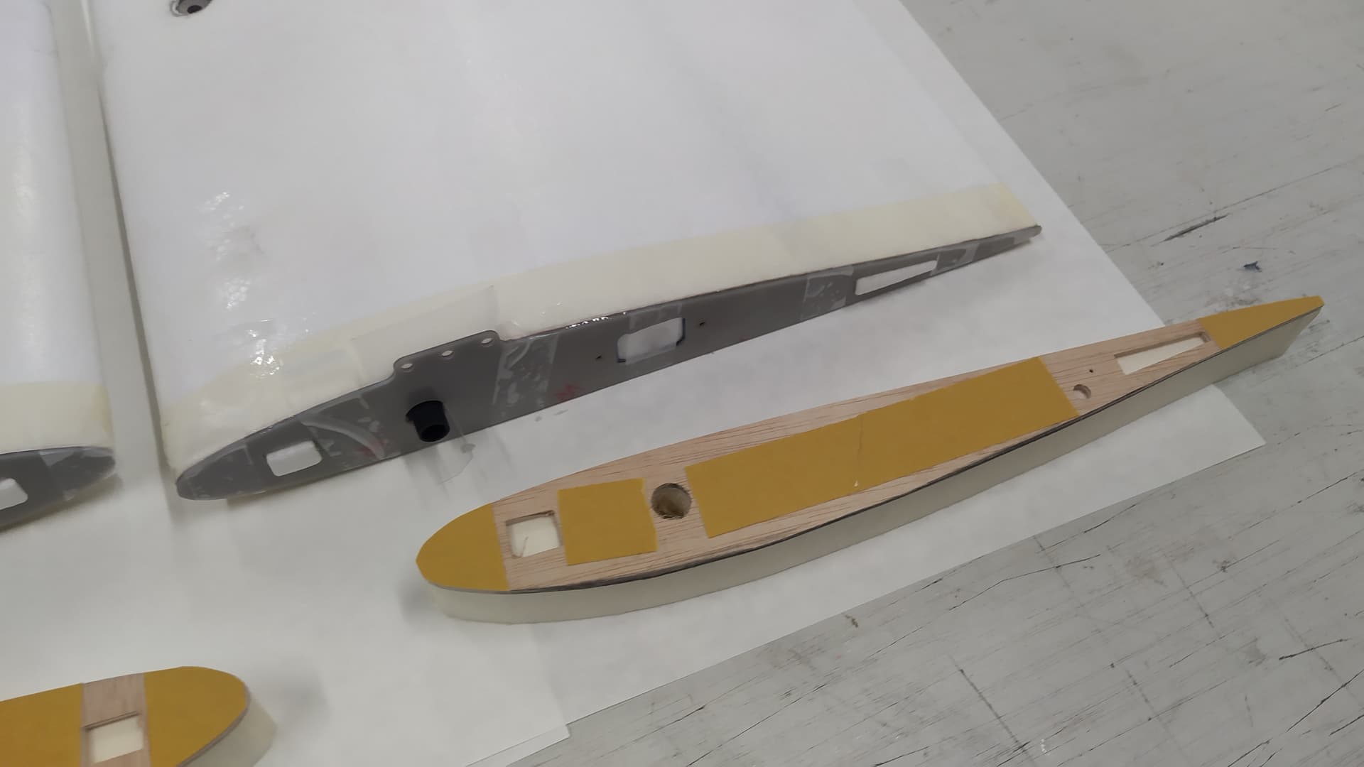
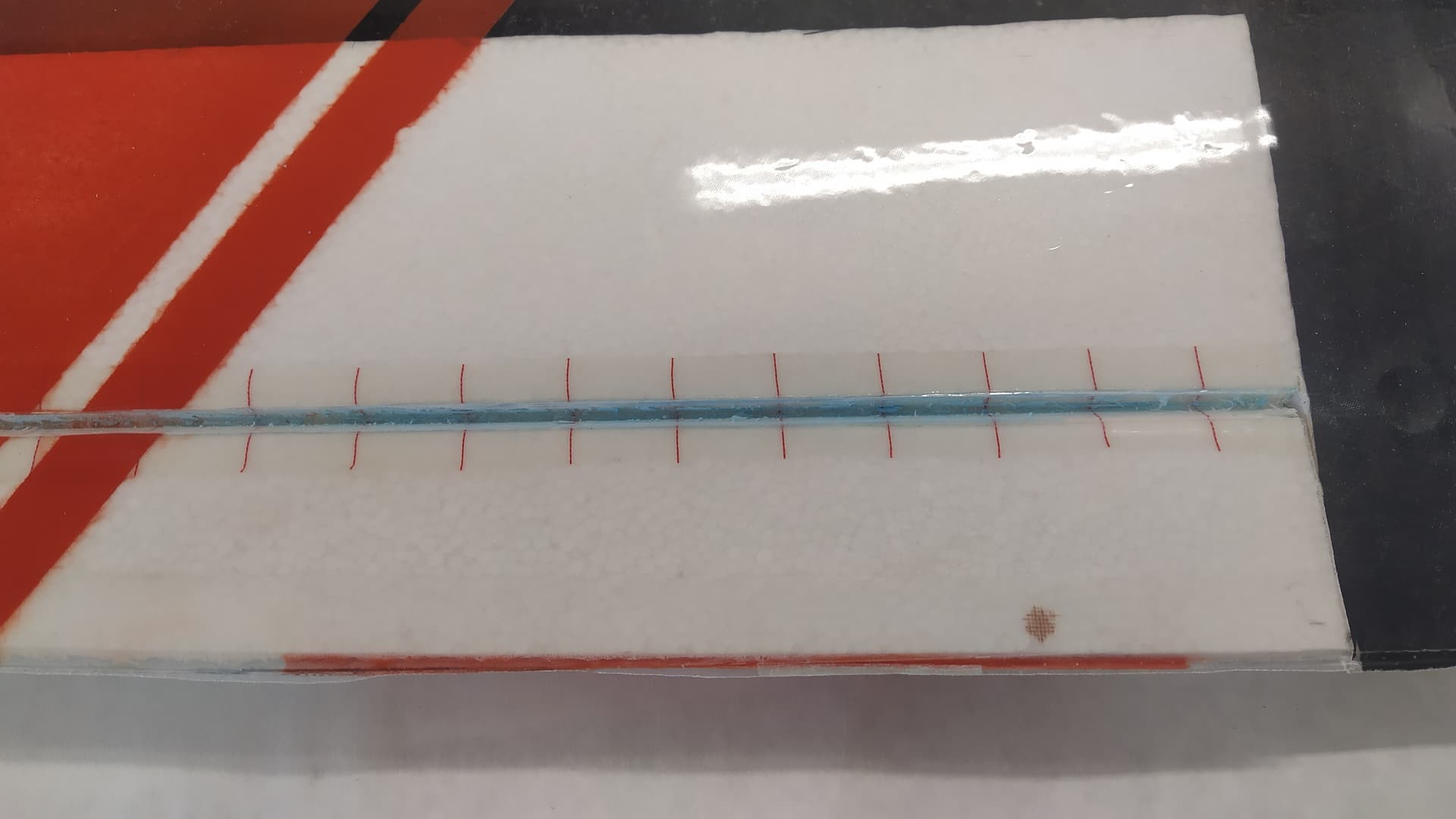
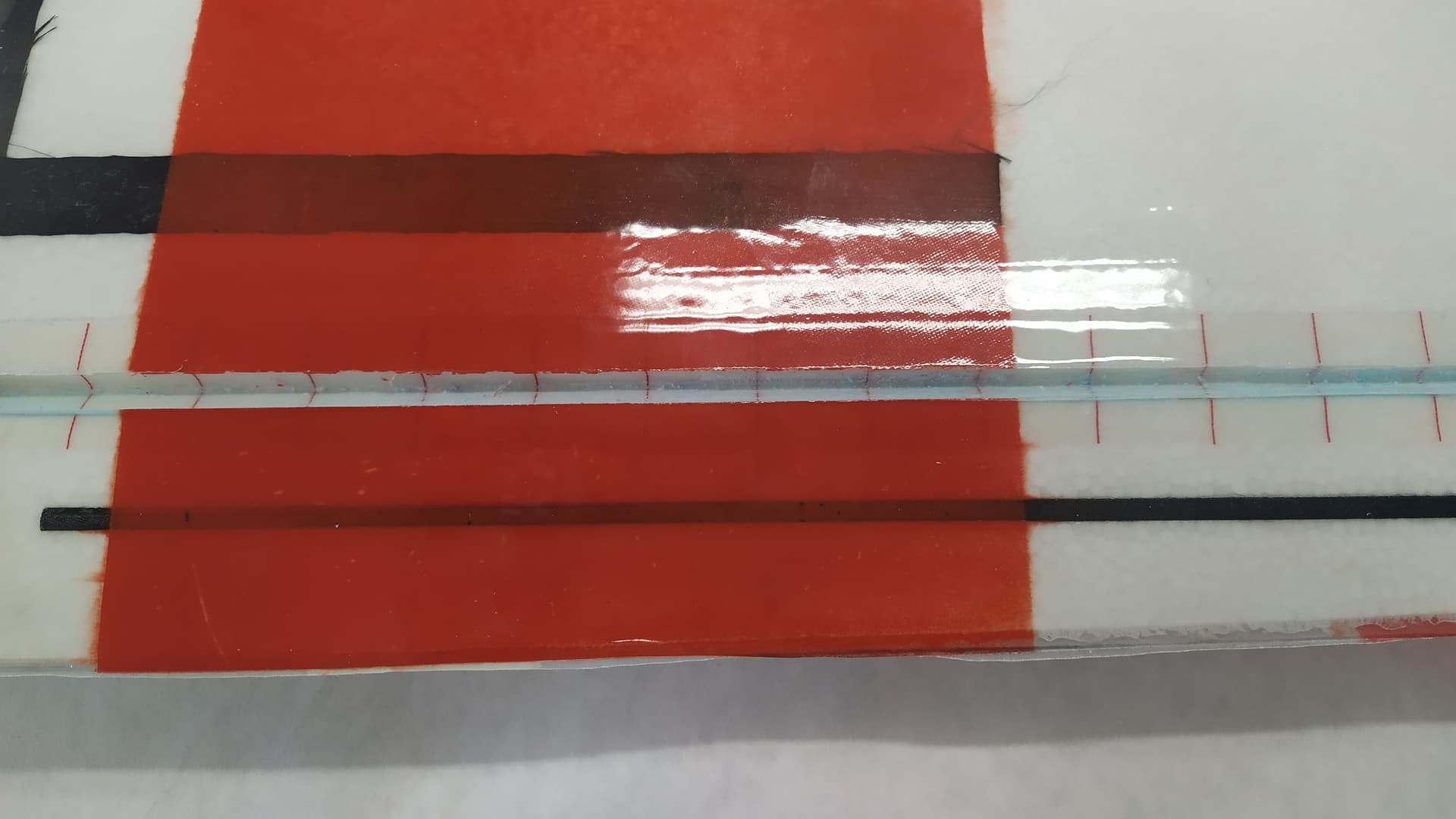
I’m going to convert a 1710mm wingspan Talon into a 4+1 VTOL.
I know it’s nothing new, but I’ll try to make it fly with Arduplane and without a bubble, and see what happens.
The maximum weight in flight according to the instructions is 3000 grams. Starting from this information, and looking at what I have in my drawers, I will carry out this project.
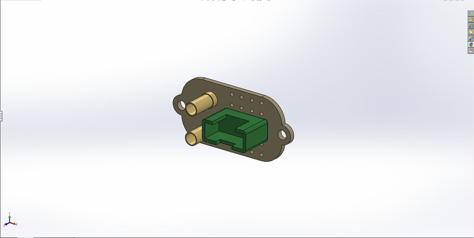
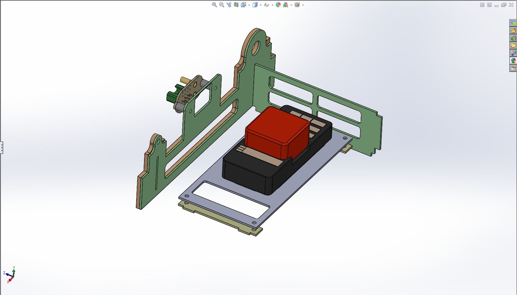
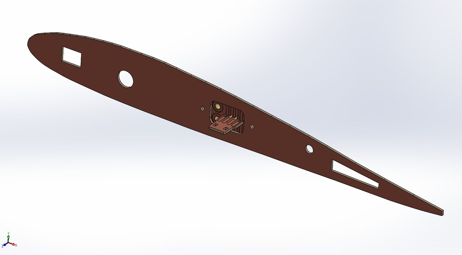
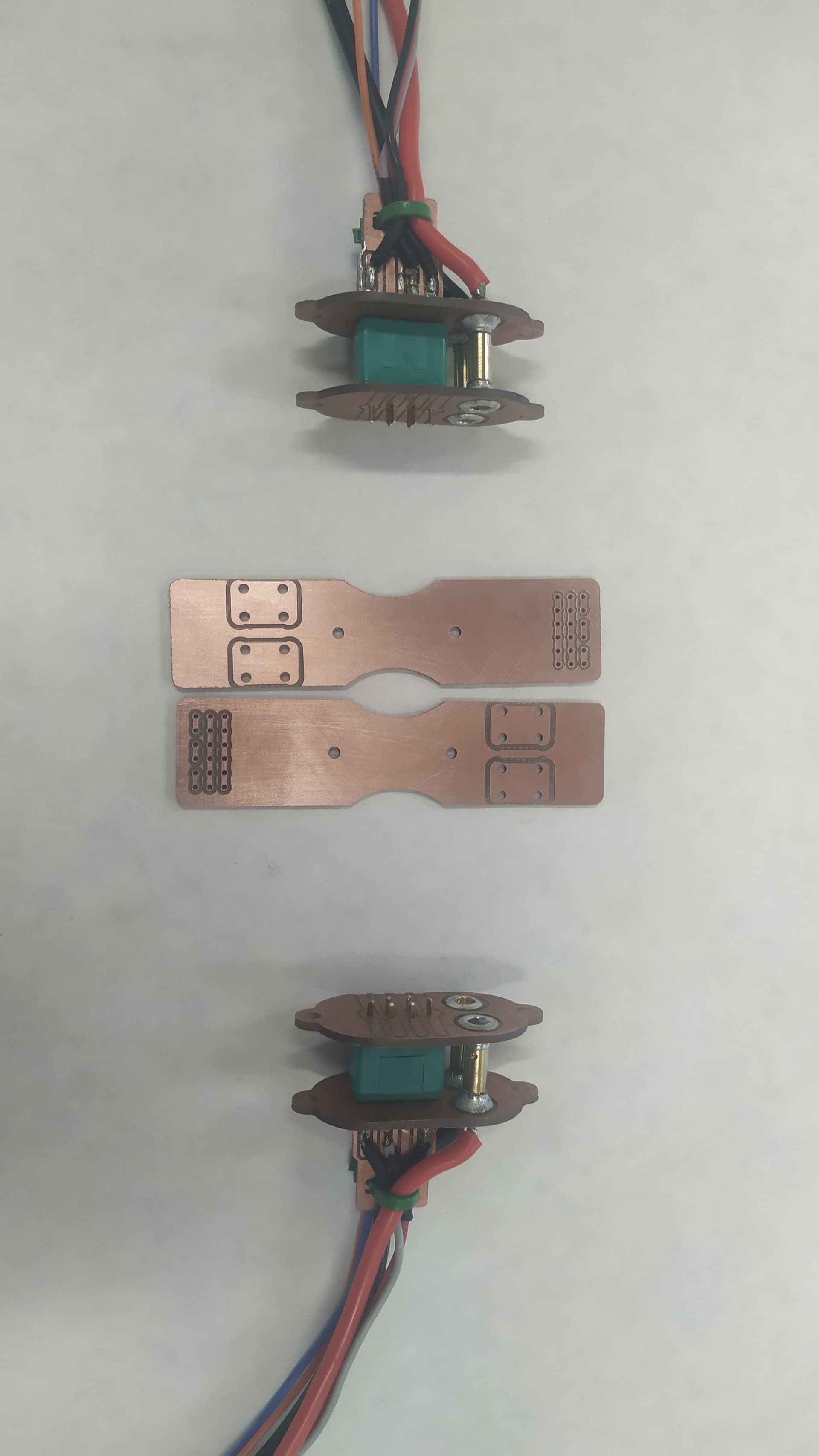
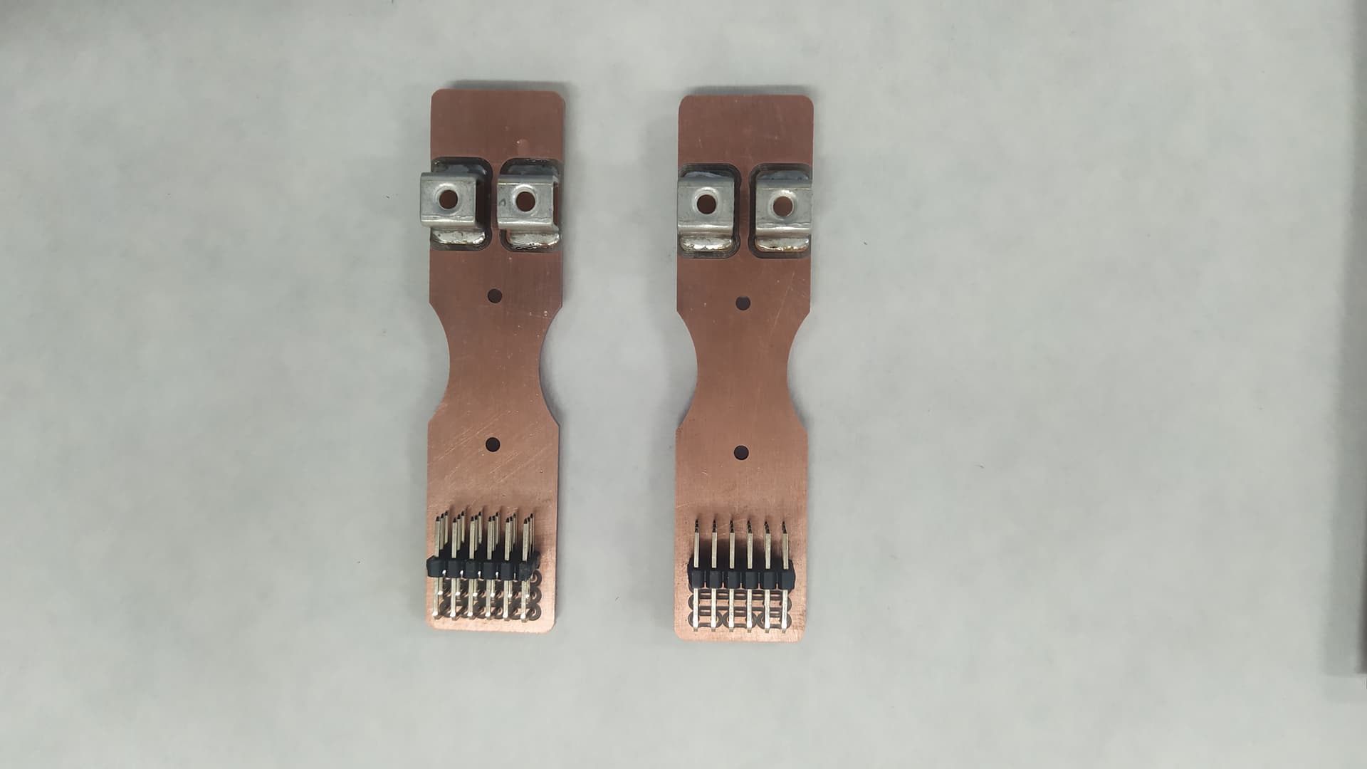
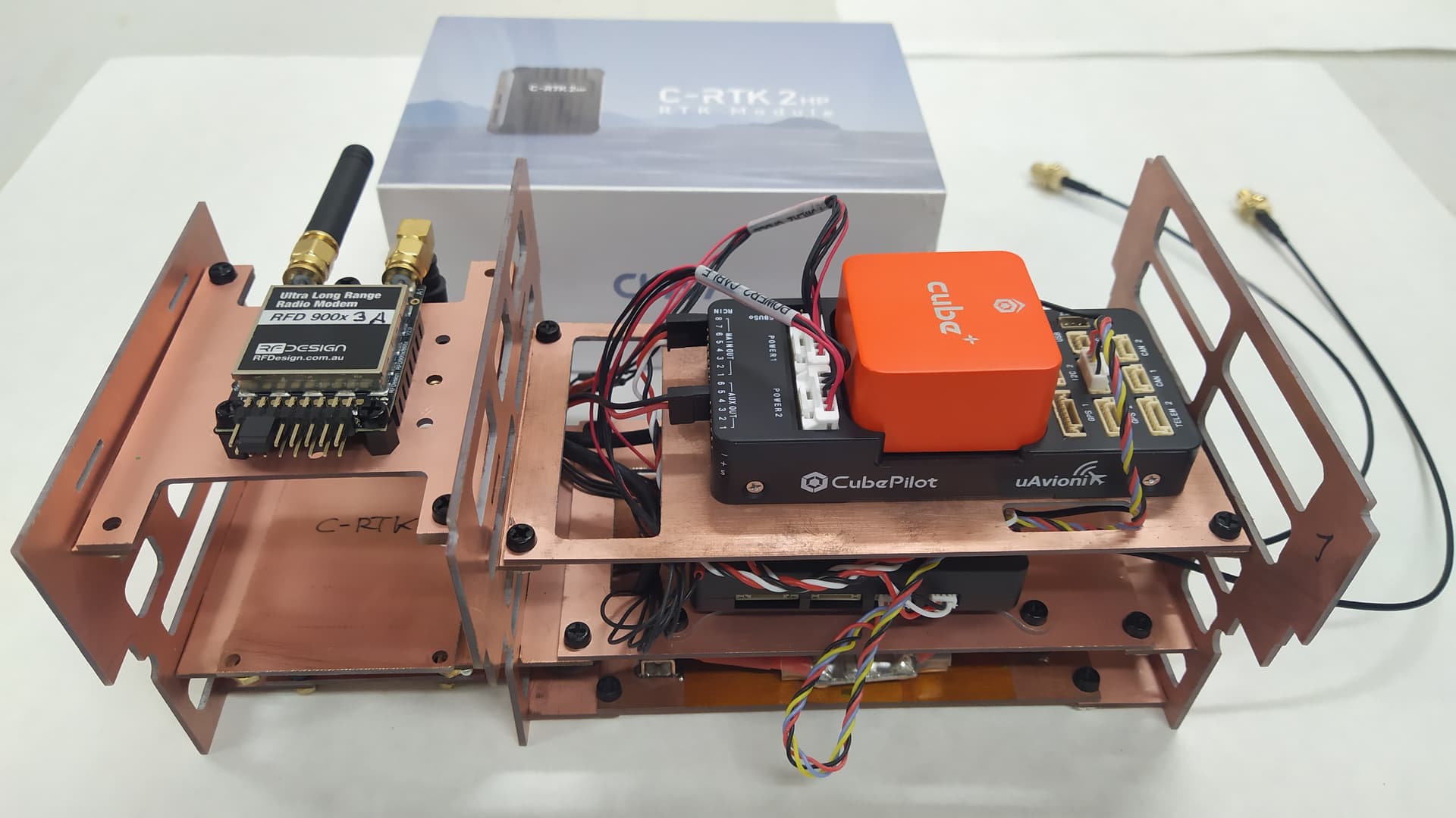
I will buy something such as the flight controller, the tubes to make the arms, the Quadplane motor mounts, connectors, cables, etc…
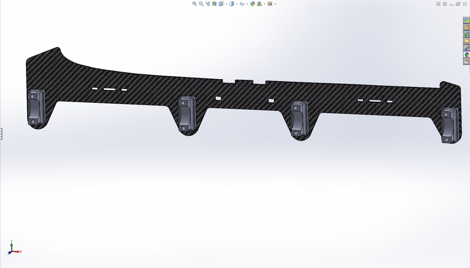
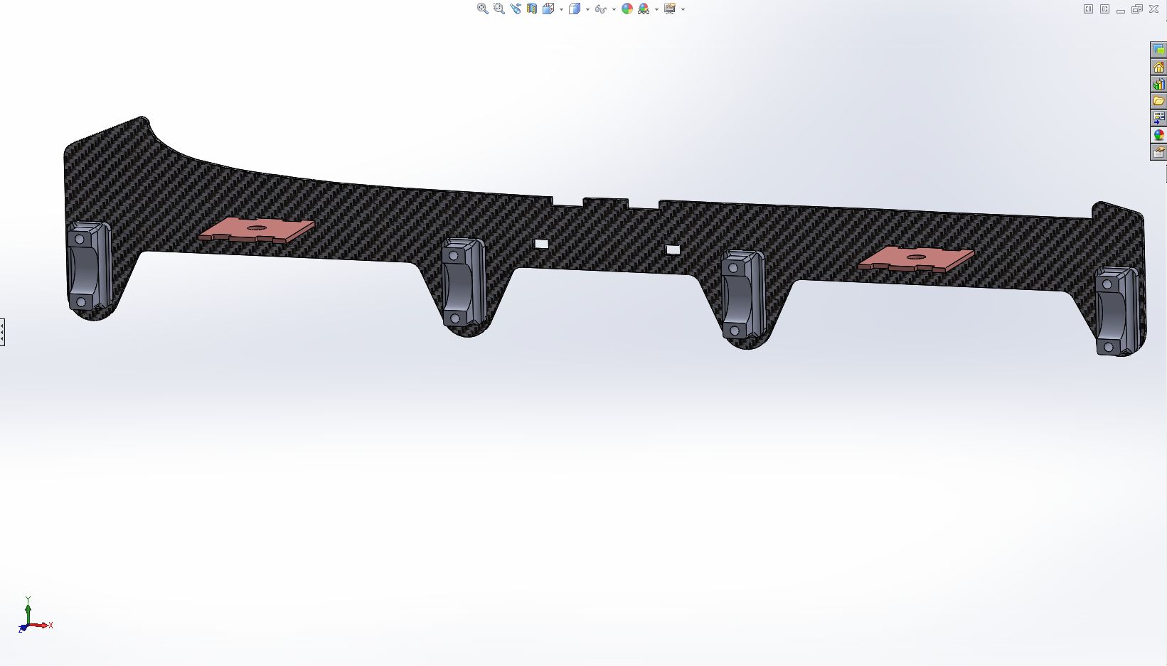
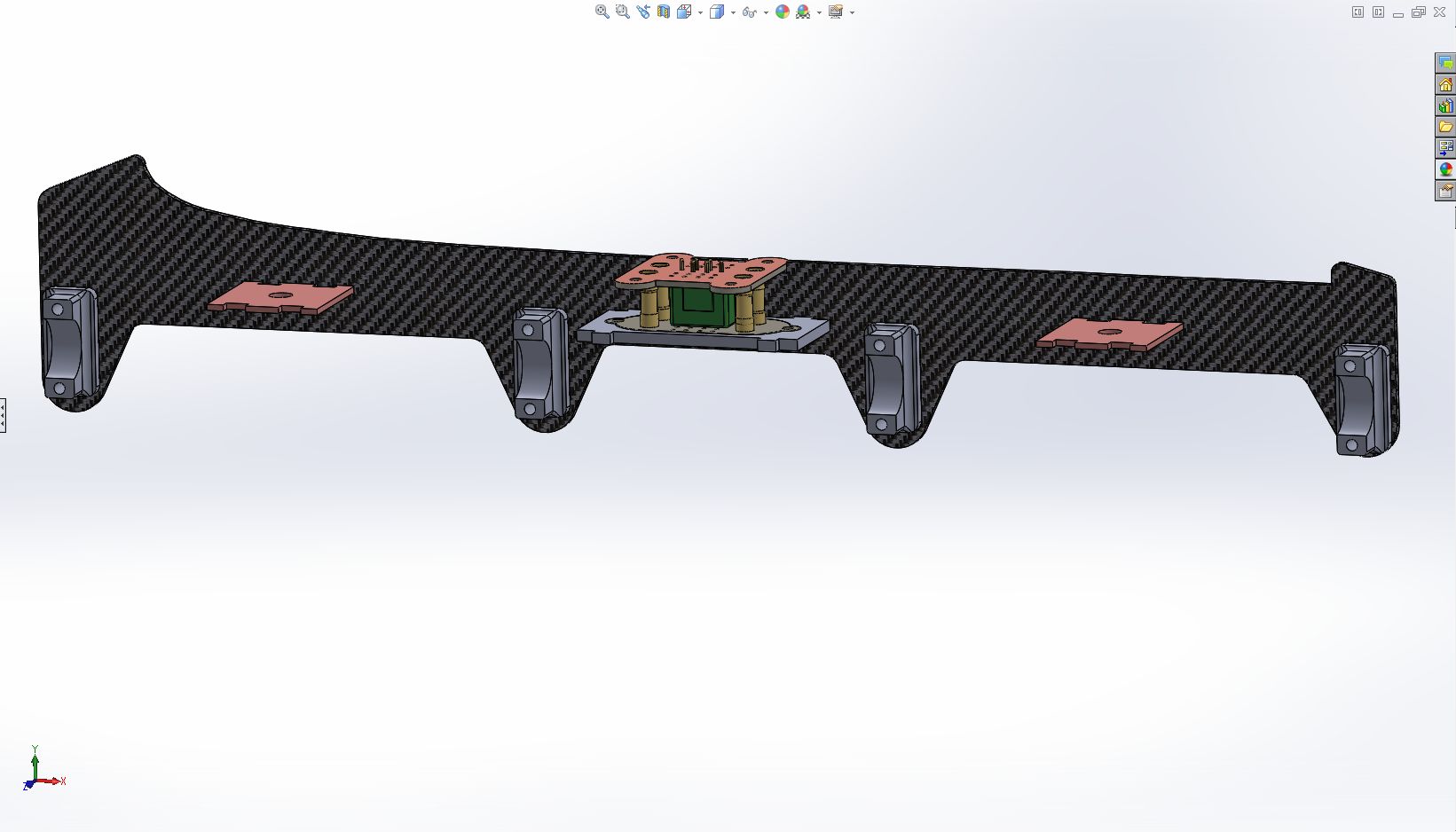
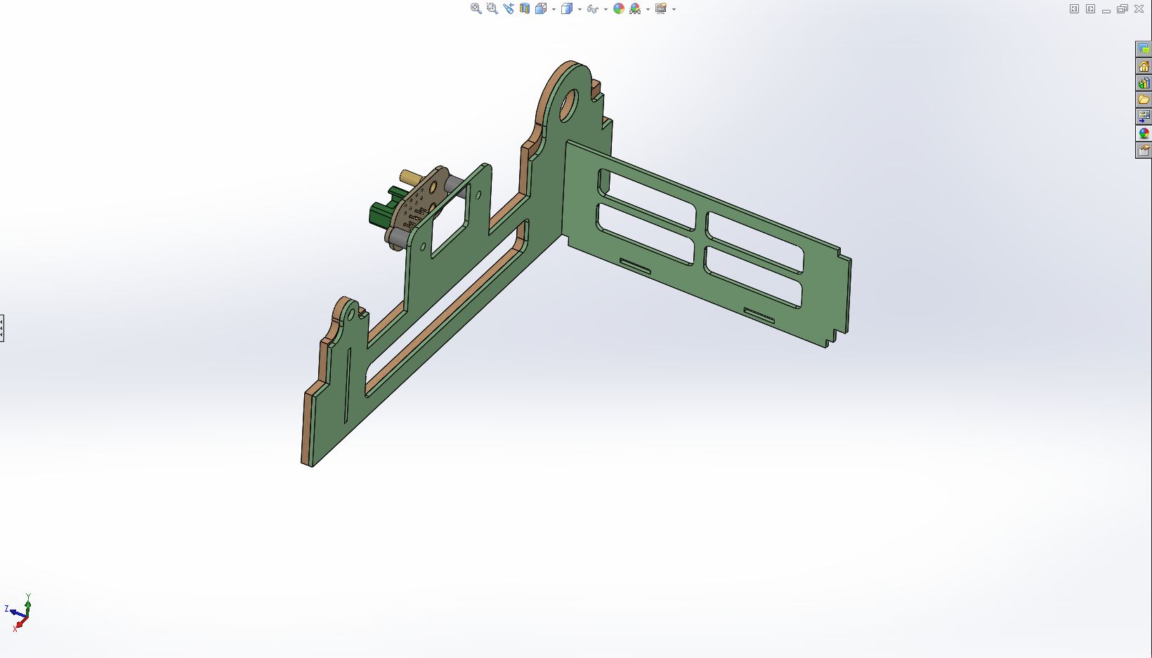
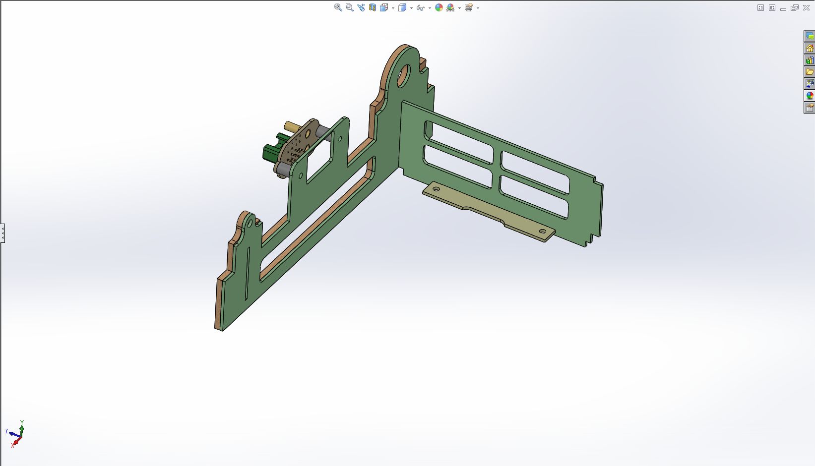
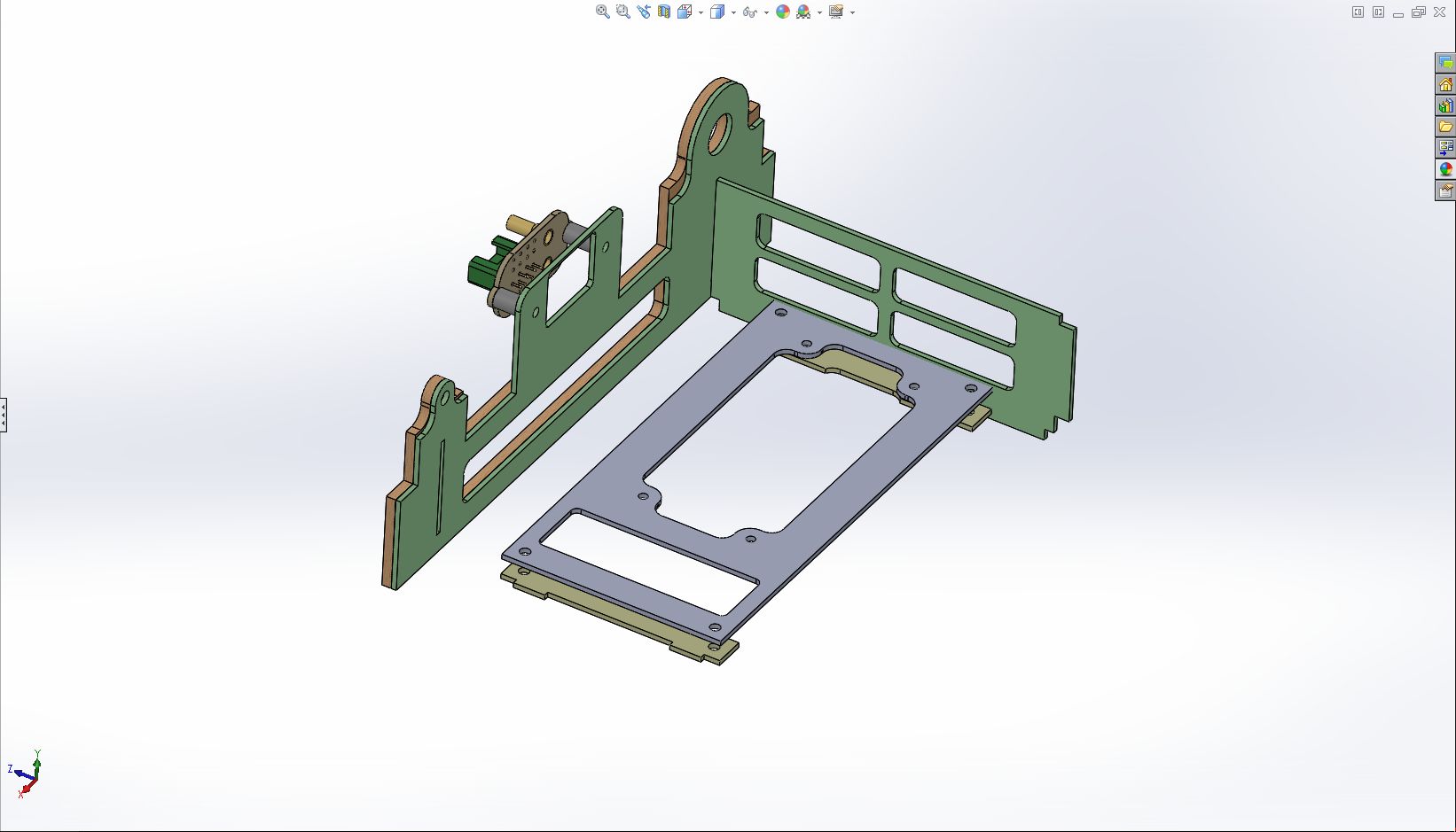
The Quad configuration will be type H.

I leave you a photo of the box.

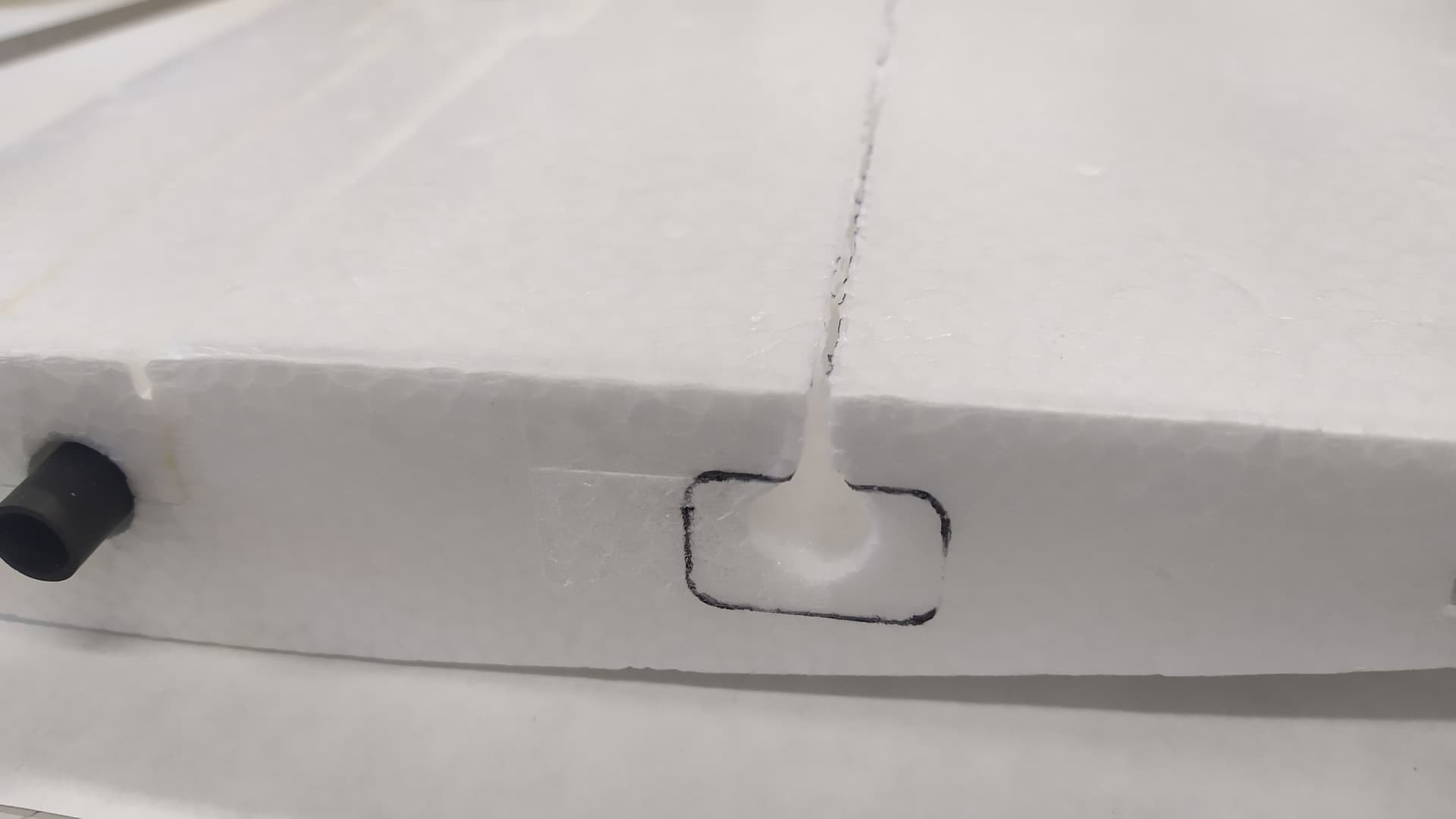
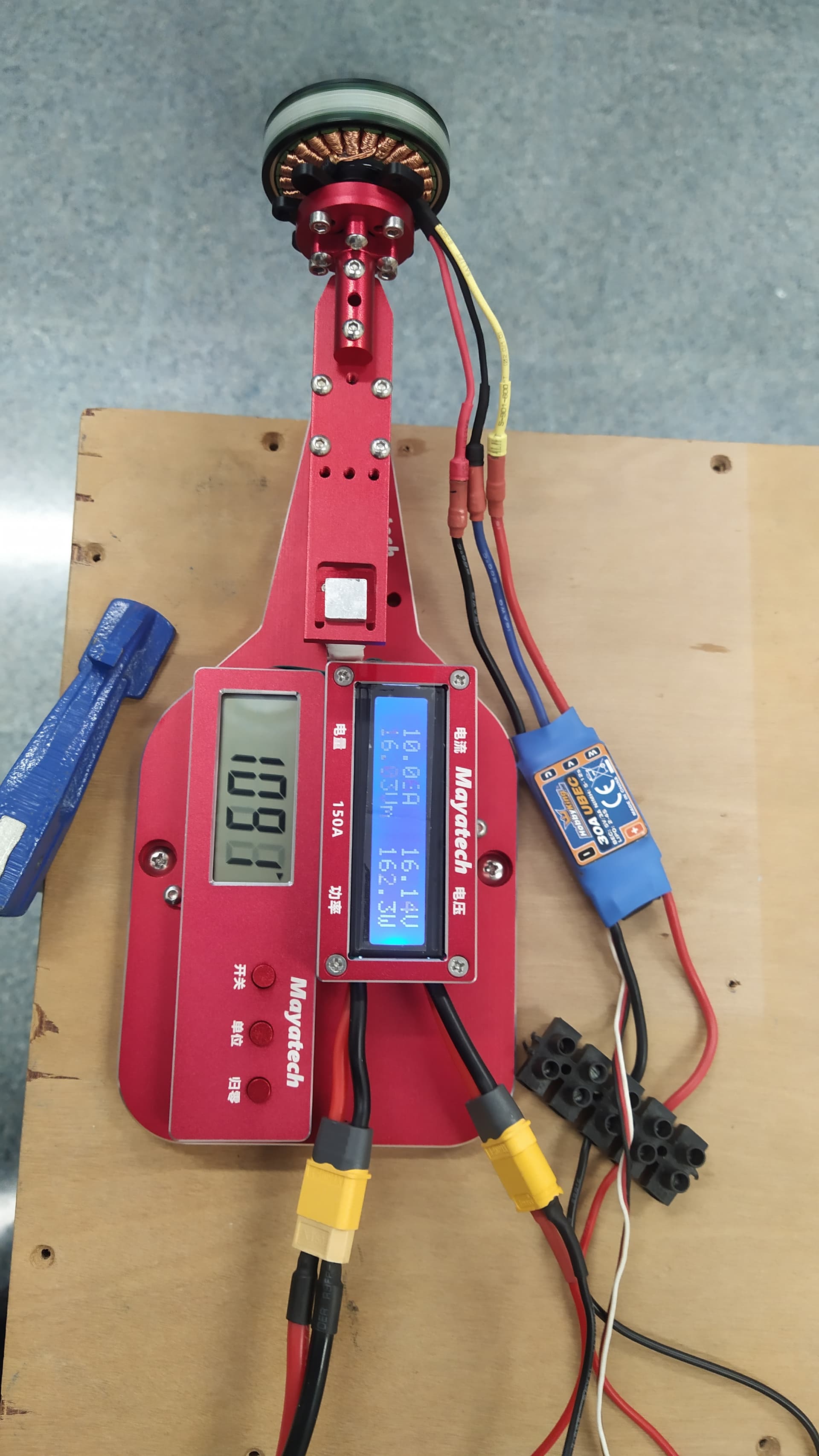
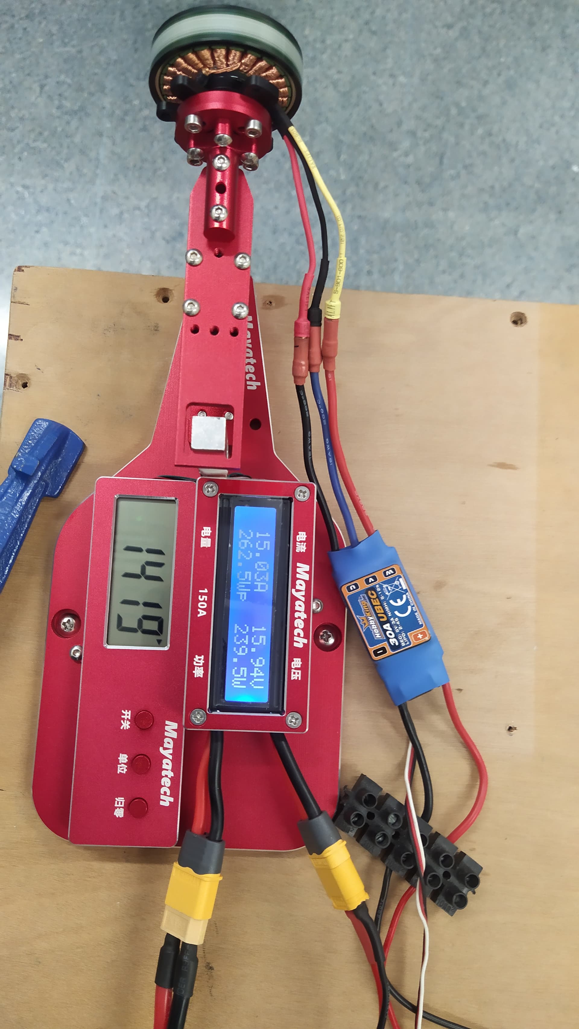
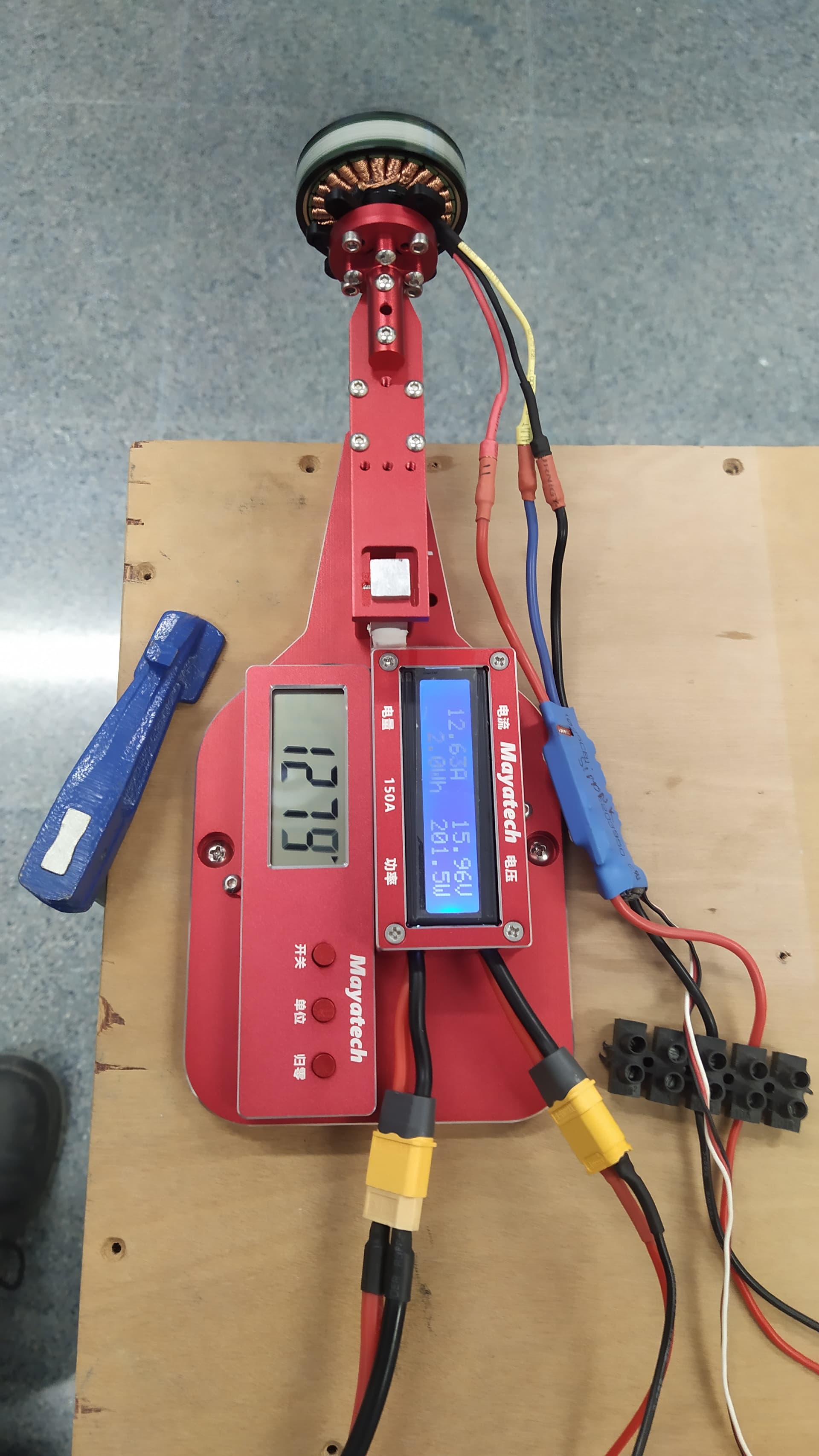
I have done some tests on my new push bench.
The motor that will surely be used will be a 490 KV multistar.
For the tests I used a 4S battery of 10,000 mAh and 15C discharge.
The propeller for this test is a 13x5.5" multicopter propeller with the following results:
50% throttle

100% throttle

The propeller for this test is a 14x5.5" multicopter propeller with the following results:
50% throttle

100% throttle

With these results and the estimated weight of just over 3300 grams, we will design the arrangement of the arms in such a way that we can install either of the two propellers depending on the final weight of the Talon VTOL and the preliminary takeoff tests.

The power-to-weight ratio with the 13x5.5" propeller is 1:1.30
The power-to-weight ratio with the 14x5.5" propeller is 1:1.52
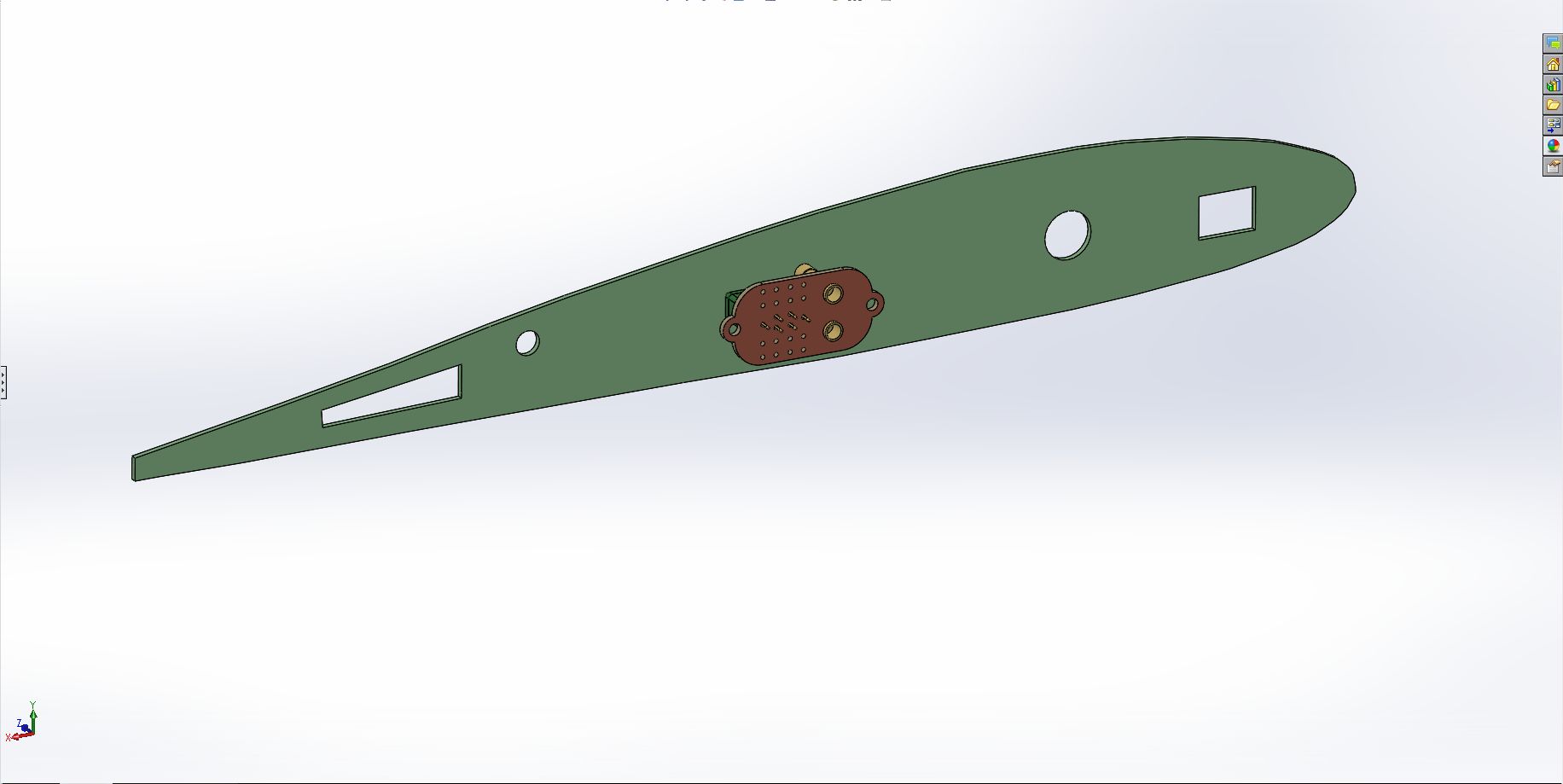
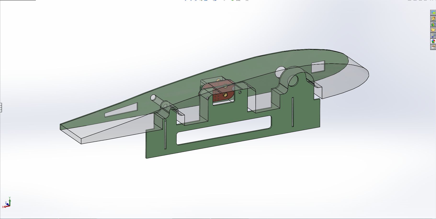
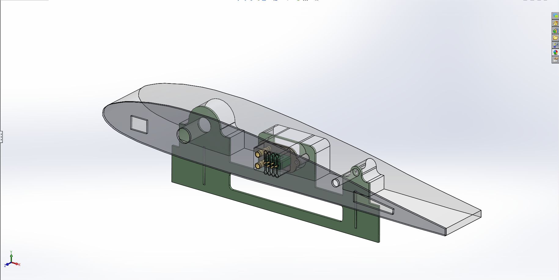
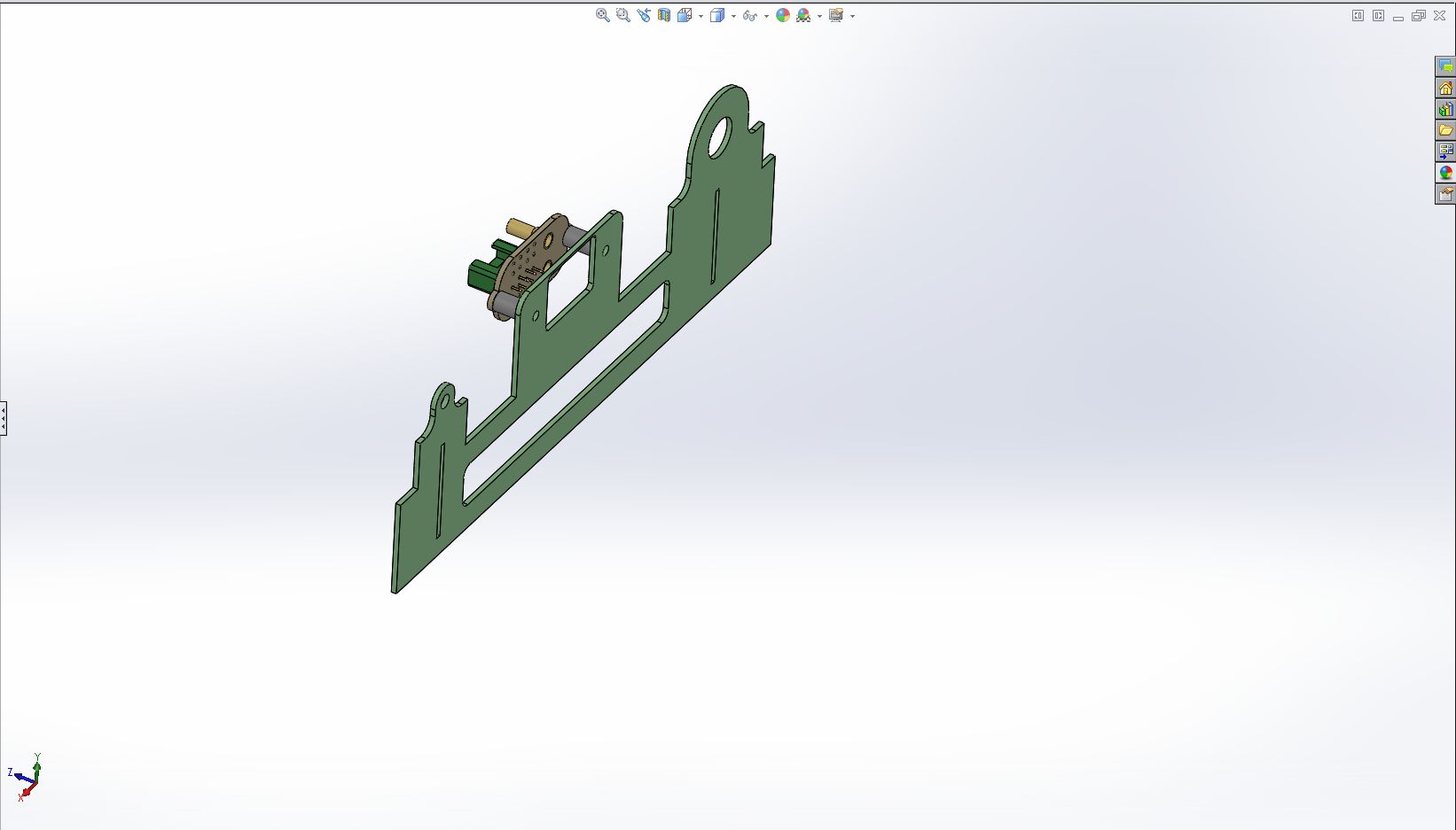
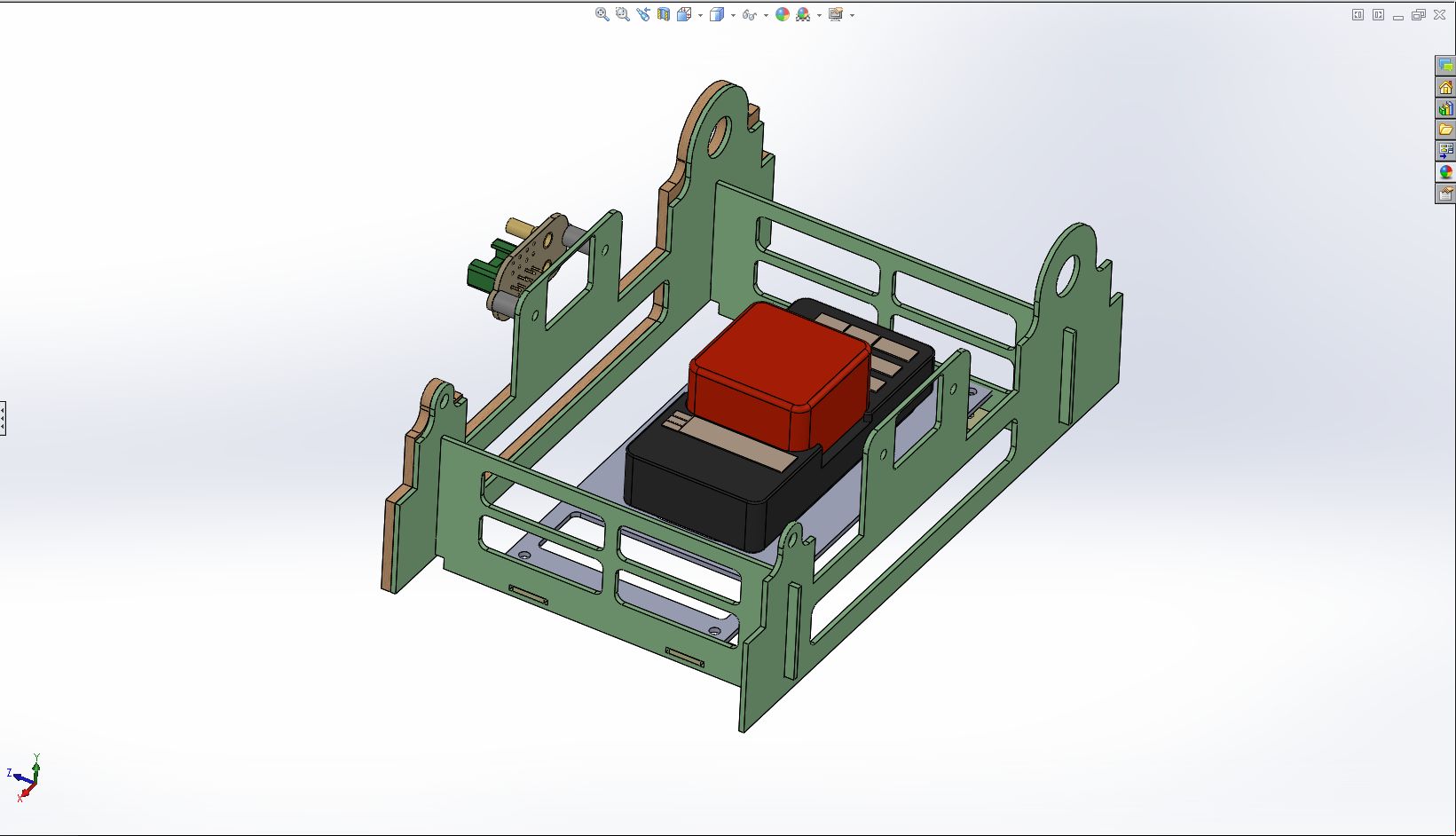
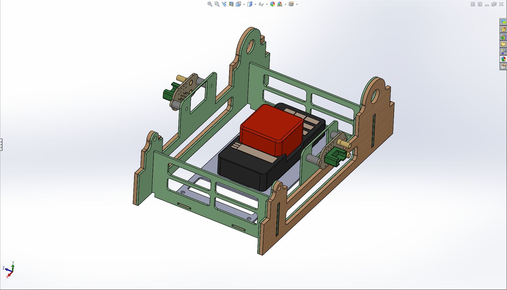
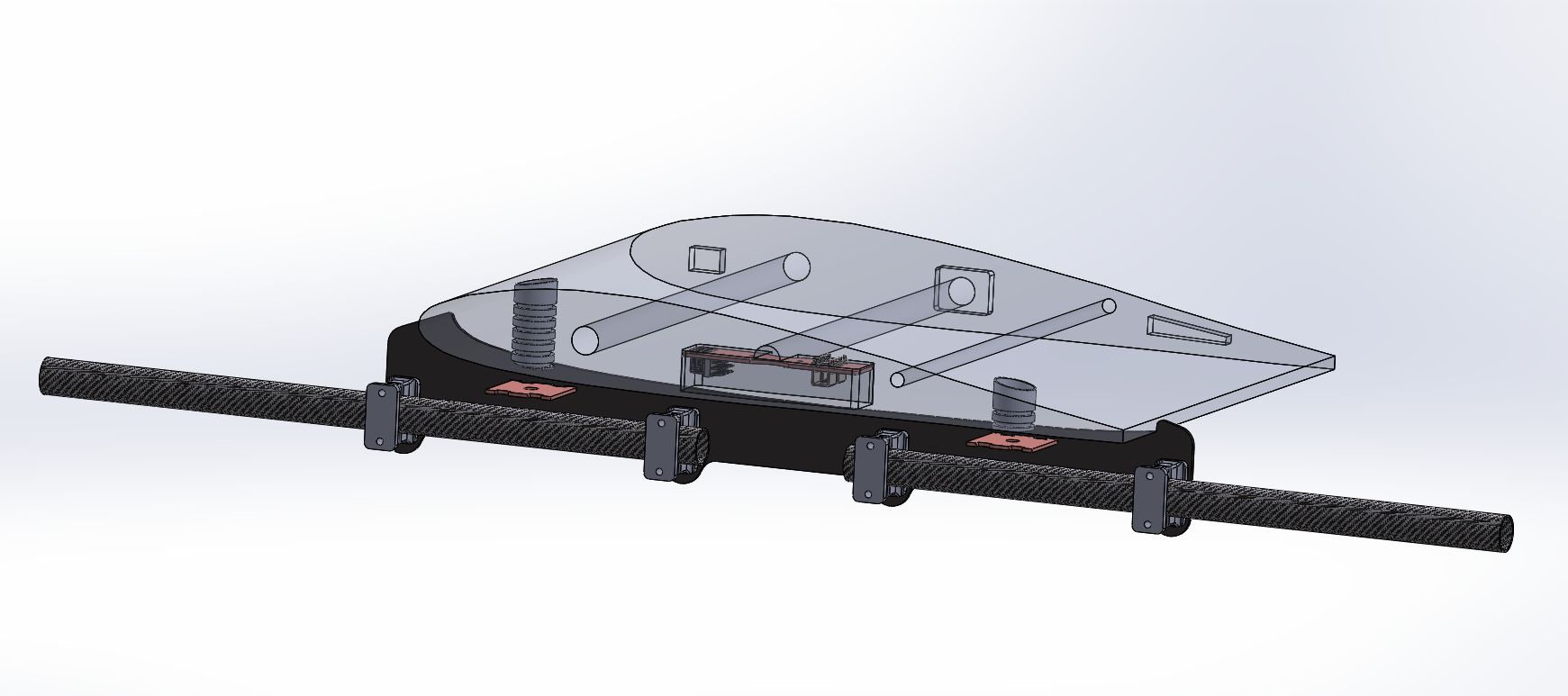
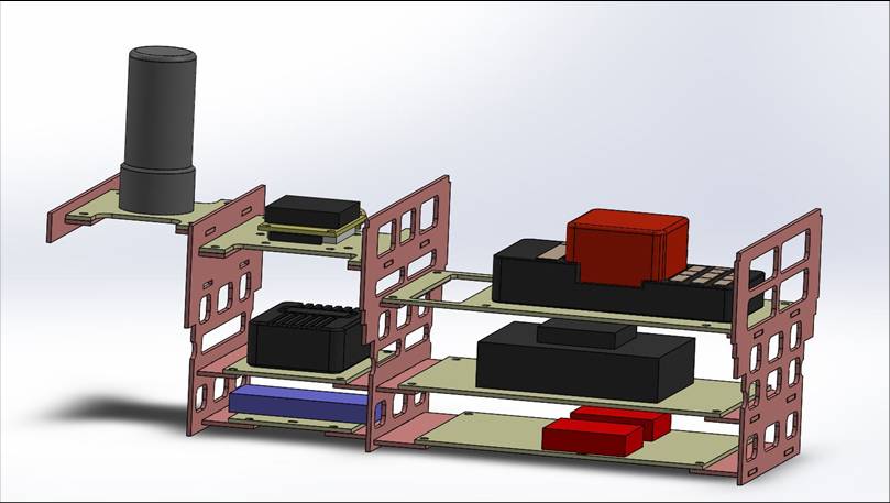
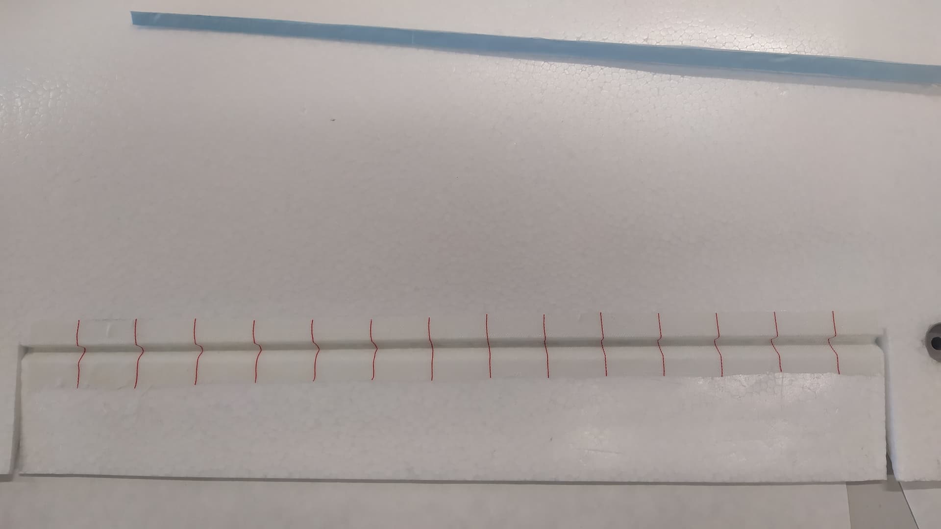
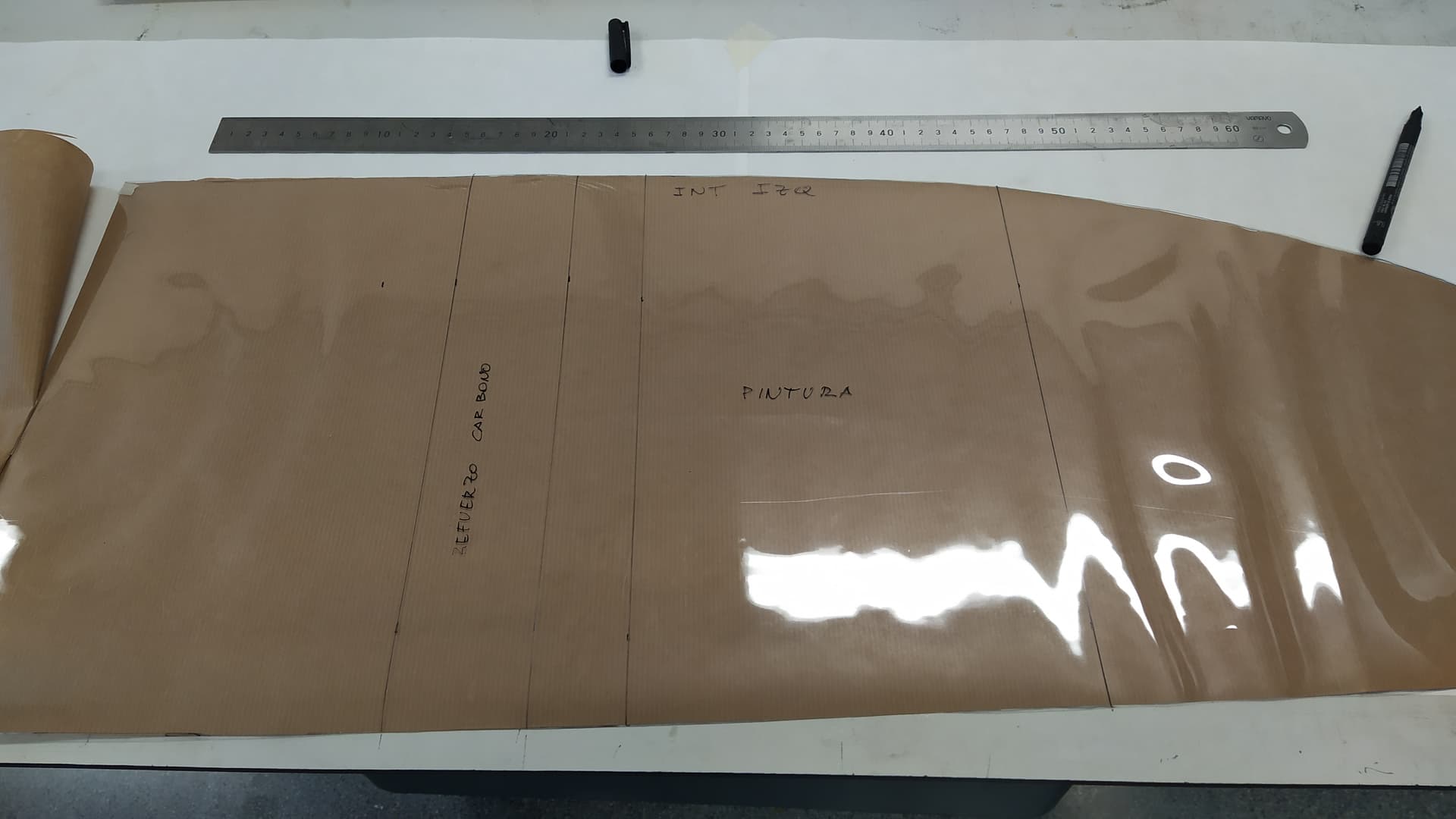
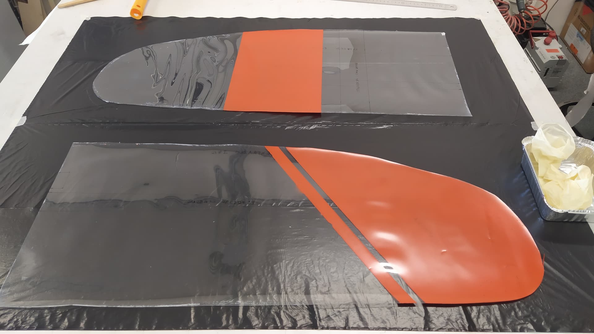
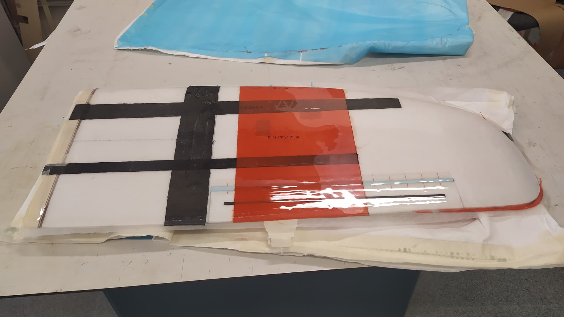
We start drawing.
All the best.
Raul.

1 Like

Hello:
Today I had some time to draw.
Following the same philosophy that is giving me such good results on the HISPANO, I have begun to design the system for attaching the engine arms to the wing.
Here I leave you the assembly process.

I keep working.
All the best.
Raul.

Hello:
I have continued with the solution of the electrical connections.
I have reproduced the way to connect the board outputs of the ESC’s, servos and power supply to the motors using a connector that will be on the gimbal of the fuselage and that will be connected when joining the wings to the fuselage.
I already have this idea well tested.
In this sequence of photos you can see the idea.
The wing will have a rib at its root, which has the MXP connector soldered where the cables of the two variators and the aileron servo are connected, as well as the two motor power connectors.

The cables that go to the arm connector are soldered directly on this rib, which is made of a single-sided printed circuit board.

This is the connecting connector between the fuselage and the wing root.

It is inside the gimbal of the fuselage.

So that the connector that will be inside the gimbal of the fuselage wing is at the correct connection distance, we will use some spacers.

The connector with its spacers is screwed to the autopilot holder plate. This plate will be glued to the inner side of the fuselage.

This is how the set looks.

The next step is the creation of the plate where we will fix the autopilot and we will also think about the distribution of the power module, the radio receiver, the telemetry, the GPS antennas, the GPS and the thrust motor ESC.

I keep working.
All the best.
Raul

Hello:
I already have the set of parts where the controller board will be mounted, for this project, unlike the motors that were in a drawer, I will spend the money and install a Cube Orange.
This is the development of the idea.

I will use the piece of wood that comes in the kit.


This piece is the one that supports the electronics, I will surely modify it to install the power module and the cable connectors that will go to the motor drives.

On top of it with some spacers is the pixhawk support plate.

And that’s how the whole thing looks.


I keep working.
All the best.
Raul.

1 Like

Hello,
I have made a modification to the arms, simplifying the connectors, which saves on material and weight.
This is the new solution:

I also included some studs that to date were made of beech wood and for this occasion they are printed with PEG in 3D printing.

I have worked on the distribution of the elements that will go inside the fuselage.
It is structured by floors which allows access to each of the components.
This is the solution I will use:

It is designed to be accessed by floors since we will only have the upper part of the fuselage to access.
The provision is as follows:
In the block on the right, in the lower tray are the power modules, I am going to use one to measure the consumption of the 4 engines in the copter phase and another for the forward engine as an airplane. The reason why I use two is because since I have had them for years, I am not clear about the consumption they support, this way I cover my health.
In the middle tray is the Siyi HM 30 receiver, I went out of my way and bought a Siyi MK 32 at RC-INNOVATIONS. This station has very good possibilities and the best thing is its price, which is moderate.
On the top tray is a Pixhawk Cube Orange, it is not the latest generation, but its price is relatively low and the best thing is that it has ADS-B. Also purchased from RC-INNOVATIONS.

In the middle block, on the lower tray, is the ESC for the advance motor.
In the middle tray is the CUAV C-RTK 2HP GPS with two antennas, this GPS is the one that will allow you to fly without a compass.

The long-distance telemetry is located on the upper tray, it is a RF Design module, the RFD868, and CE certified. I have also bought the pair at RC-INNOVATIONS, which has them in stock and at a good price.

In the attic of the last block (forgive the irony) one of the GPS antennas is located, I will place the other in the nose. The cables connecting the GPS to the antennas are 500 mm so it takes plenty.

I’ll tell you why I have work to first read, like a good Spanish, the manuals of all the material that is new to me, understand everything and configure it. It will be fun.

Regards
Raul

1 Like

Hello:
I start doing something with my hands and not just drawing.
There is a recess on the ailerons, it is supposed to be for reinforcement with a plenum, but none comes in the kit, so I put a 5x1 mm carbon one.

I have made a counter mold of the hinge for when we put the aileron hinge on.

I cut out the power cables for motors, drives and servos, using the hot wire tool.

I make the hole where I will house the connection plate for the motors, drives and servo.

I proceed to place the arm fastening pins.

For its correct positioning we use the arms that I have previously cut in carbon.

I cover the gaps with foam.

And I place the peel ply hinge.

The next step will be to prepare the wing templates for fiberboarding.

Regards,
Raúl.

Hello:
I have made a modification to the root rib connection system, before starting to prepare the wing for fiber coating.


Instead of directly soldering the Multiplex connector and the power connection pins directly to the root rib, I made a connector with a plate where the cables will be soldered.
This is the idea.

This connector will be screwed to the root rib, this allows me to always have access to a possible change of cables or revision of them.
The set looks like this once assembled.

I don’t know what you think but I like it much more than the previous solution.
Regards,
Raúl

Hello:
I have cut the root ribs to progress with the wings.
I have added a series of holes that will help me position the center of gravity.
I have welded the nuts that will allow the power distribution connector to be attached to motors, drives and servos.

With epoxy I glue the ribs to the wings.

To prevent the vacuum from damaging the wing root profile, I cut a piece of foam about 3 cm long with the wing profile and glue it with double-sided tape to the root rib.

Now I reinforce the leading and trailing edges with 50 g/m2 fiberglass.

Detail of the trailing edge.

With this I now have the wings ready to be fiberfied.

Regards,
Raúl

Hello,
I have prepared the acetates to enfibrate.
To remove the shape of the roll, I put the four acetates in the oven at 45ºC for 24 hours and it worked perfectly.
On the opposite side to the waxed one (just one coat and polish), I have drawn where the masks for the paint will go.

I have used red spray for decoration.

For this occasion I have prepared an aerating film for the entire wing.

To which, I have put kitchen paper.

Specifically 3 layers.

We begin to fiber.

I take the wing out of the vacuum bag that has been in the stove for 48 hours at 45º.

We remove the aerator from the extrados and intrados.

We remove the acetates and eliminate the foam from the hinges.

Now to take some more time to make the other wing.

I keep working.
All the best.
Raul.

Hello,
Well, these days I have been working on the connection plates for the wings and fuselage.

I have cut all the plates and plate holders except the one for the GPS antenna.

And I have tested how the assembly of the whole looks.

I hope that all the connections are not super compressed, we will see when the truth comes.

I keep working.

Regards,
Raul

1 Like