I am looking for two solutions and wondering if anyone has past experience addressing this problem in the past.
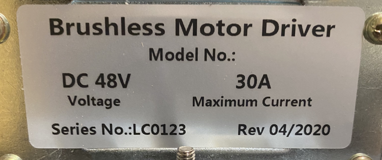
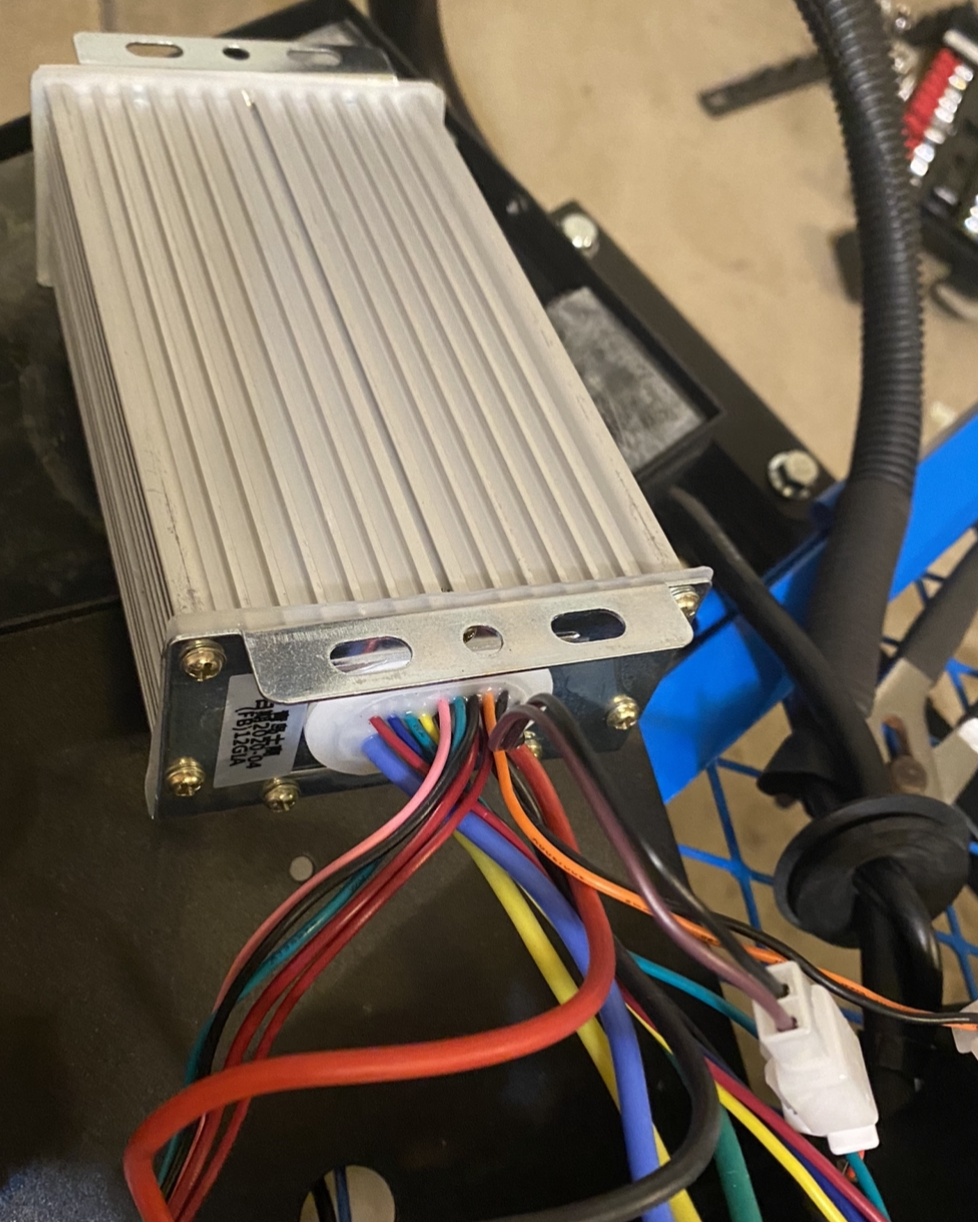
I have a fairly large size Rover. Its uses a large scale 48V, 30A brushless DC drive system.
What could be the right type of speed sensor I can use with it? I know about hall sensors, but is there a better solution out there that can determine the speed of the rover more accurately so it can be controlled to move at a very constant speed as possible?
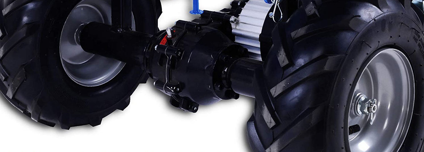
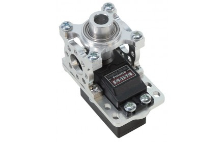
The wheels of the rover are simply driven by a drive system.
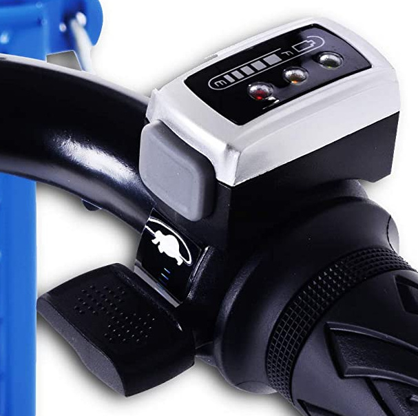
The Rover has a built in speed controller. The speed of the Rover is controlled right now using a manual Potentiometer (I don’t know the value of the pot at this point). The 48 VDC brushless drive system is pretty heavy duty and it comes with its own electronics for speed control, reverse and forward and has potentiometer for speed control.
As I want the Pixhawk to control the speed of the Rover, is there an off the shelf Potentiometer replacement solution out there that would work with Pixhawk?
a) One possible solution is to use a Servo block and keep the analog potentiometer as is.
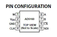
b) Another solution will be to use something like AD5160BRJZ50 s an 8-pin digital potentiometer. I have never used it before, so not sure what the circuitry would look like.
How do you plan to use your ‘speed sensor’ with Ardurover? Is this sensor going to give you something more than the velocity reported by the GPS which should be better than 0.1m/s - or are you planning to not use a GPS?
There are multiple ways in which you could possibly emulate the existing throttle input to your motor controller but how you do this would depend on what knowledge and resources you have. At the end of the day, it is likely easier to buy an off the shelf controller that accepts one of the outputs from your FC hardware.
I totally forgot about the GPS That solves the speed accuracy problem.
Now comes the trickiest part. See above, I made some changes to the original post above.
How does Pixhawk typically controls the speed of a Rover? I have actually never used Pixhawk for Rovers before, so just beginning to learn its capabilities in Rover setup (I am well familiar with plane and Copter use)
It appear Ardupilot controls the speed of the motor directly. In my case it would not work. The 48 VDC brushless drive system is pretty heavy duty and it comes with its own electronics for speed control, reverse and forward and has potentiometer for speed control.
The Pixhawk typically controls the motors on rovers in much the same way that it does on copters and planes. You have the option of PWM, CAN, SBUS… In your case you are likely looking for a variable voltage output over some range. This is not directly supported. Do you know what the voltage output range of the throttle is? How is reverse handled? It would seem likely that you will require a mcu such as an arduino to interface with the Pixhawk and produce the required output for your motor controller. This would be reasonably straight forward if you have experience with such things.
 That solves the speed accuracy problem.