Hi all, I have a RX Jumper R1 + plus and I would like to use yaapu script with FC omnibus F4 nano V6.0. and radiomaster.
I need the outpus on S.port and therefore with F4 a non-inverting pad on the rx. I connected the serial TX1 (like in wiki) of the FC to the central pin of U5 (as in the picture pin 2), but I cannot read the telemetry data on S.port. On the RX I have not updated the FW.
What can I try?
Same RX works fine (normal connect with connector) with kakute F4 and S.port TLM
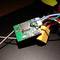
I bought a couple of these max3232 cheap china boards from ebay and the first one has worked for about a year and does not get hot, never tried the second one till this week. It was not working, so I put a scope on it and found some of the through holes on the board (where you connect the wires to on the end of the board) were not making contact. I had soldered the two diodes to the bottom this time and the wires to the top.
And the diode that is connected to the S.Port was open (because of the open via) was showing the signal coming out of the rs3232 as +6 and -6 volts swing, then I remember rs232 signals are +/- voltages. S.Port is definitly not +/- voltages. When I got the diode connected properly, the minus portion was gone, I think it was being blocked by the diode, but the positive voltage was 6V going into the S.Port, that does not seem correct, thoughts?
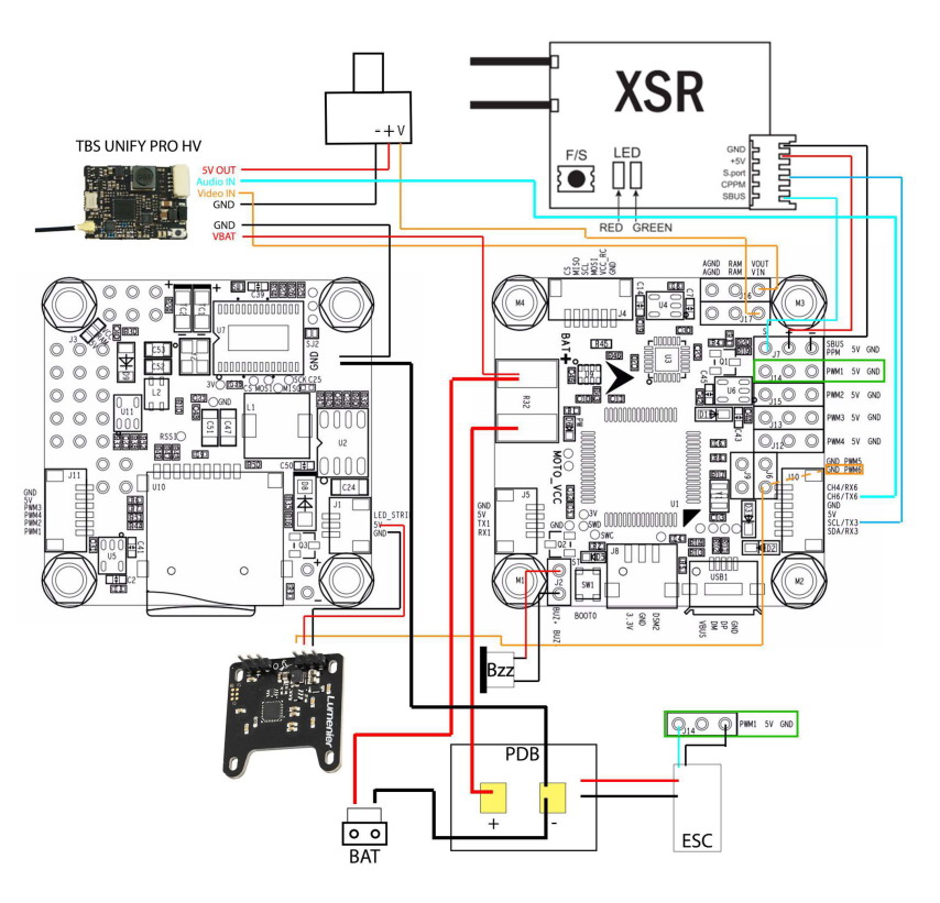
I bought a couple Omnibus F4 V3 Pro flight controllers for use with AC and AP. I found this wire diagram on the net (not on Omnibus/Airbot) and it shows S.Port of a XSR “directly” connected to UART3 = I2C or Tx3/Rx3 (serial2 in MP) without a converter.
maybe there is some problem with the max3232 chip. we have made a converter cable like yours, it does not work too. so I bought this one. it does work. https://www.amazon.com/dp/B07KJFWTCB
I am trying to connect my omnibus F4 nano v6.0 (6.0 version arducopter stable 4.0.5) to external inverter to have the yappu script on my master radio. My RX is a Jumper R1 + with S.port (tested on kakute F4 and yappu works fine). I have tried all the protocols on serial 1 of the FC omnibus (10, 23,4 baud rate 115,57 serial option 160, 0), but on the radio I don’t see the additional telemetry data. What can I try? I also connected TX1 output on pad RX and on TX of external inverter, but without success. Thanks
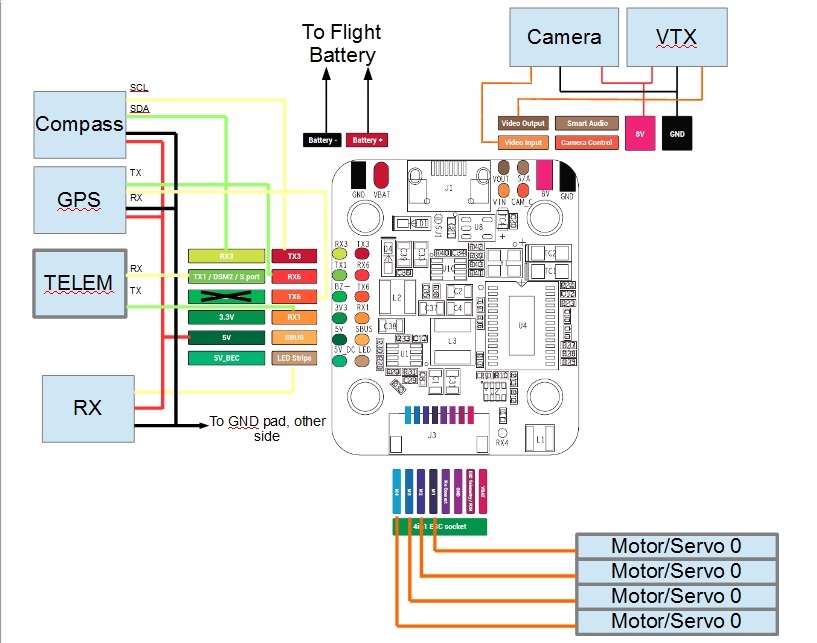
I copied this diagram from the Ardupilot docs and took out the additional FrSky “diode on a circuit board” item and drew in how to add the diode yourself. Use a 1N4001 or 1N914, really any diode will do except an LED.
You can easily find connectors that fit onto the pins, or solder directly to the pins. You can even remove the connectors and solder directly to the board if you’re good enough
I’ve found that the S-Port ground (0v) wire is optional too, since the flight controller, RC receiver and TTL converter all have a common ground anyway.
And these settings worked as per the suggestion in the docs:
SERIALx_BAUD,57
SERIALx_OPTIONS,160
SERIALx_PROTOCOL,10
Hi I am trying to connect yapoo telemetry to Horus X10s express. I have Cube Orange, yaapo cable from aliexpress, Archer GR8, open tx 2.3.10, yapoo telemetry script installed on Horus X10S.
Yaapo cable is connected to Telemetry 1 connector so I am changing Serial_Protocol - 10 and tried all different options for SERIAL1_OPTIONS but without success. I can’t discover new sensors on telemetry screen. I also tried RC_OPTIONS - 8but didn’t help. Anyone with similar setup can help ?
Hello, is anyone else having or had problems with the max3232 converter? I am connecting the tx(out) from cube to ttl side, arrow in, and the rx (in)from cube to the arrow out from ttl side, and I cant get telemetry readings and the chip gets hot very quickly, I am using a diode in series with vcc
I changed to another chip and its no getting hotter anymore, but I still can’t get telemetry data , can somebody please help? The max3232 is wired just like the guide, connected to the telemetry 2(Serial2 in mission planner with the baud to 57600 and the protocol set to 10, its the only port set to 10) I am using a frsky r9 receiver .
Can someone please help? I have no idea what could be the problem
After struggling with those MAX3232 from far east (some really get hot ), I connect a DVM and measure the current, those boards draw. With the good ones from China I see here between 10 to 15 mA. Ordered some MAX3232 from MAXIM and shall solder one on a board from China for comparison.