You can not use the black wire on the Sport receiver X8R, only yellow, as - and + and so used to connect to the control channel.
Having a Ground Reference (black) is always a good practice, that is why it is used
- and + in the Sport connector are needed to power external sensors. In the wiring diagram of the above, there is no need for such a connection. For example, it works without problems through one wire (yellow).
if you need FrSky sensors in line with this inverter then remove the power line coming from the PixHawk serial connection, and have everything powered from the X8R receiver, both the inverter and the FrSky sensors.
Again, one single power line to the inverter
Hi. Very helpful notes thanks. Can you confirm the wiring plan from the TTL side of the converter to the DF13 plug. Your photo shows two black wires. Which ones goes where ?.
This image clarifies the connections on the DF13 side RX/TX/5V/GND - Connect to the appropriate pins on the PixHawk, ie RX to TX, TX to RX, 5V to 5V and GND to GND
The “normal” plug will look like
1 Like
I’m using a NAVIO2 with copter 3.6.8 and a taranis QX7. Since I’m using the NAVIO2’s UART for something else, I’d like to get this setup working through the USB connection, and I think I’m mostly there. I used a 3.3V FTDI cable to do this. Since the signals need to be inverted, I used FTDI’s FT_PROG to invert the logic on RX and TX. The TX signal passes through a diode before the two signals are connected into one wire and sent into the X8R receiver (as described in the first post of this thread).
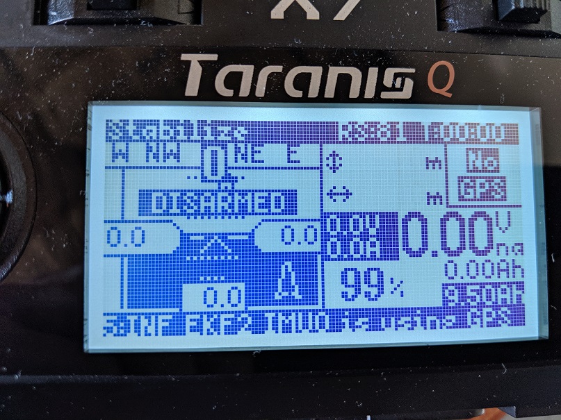
On the taranis, it seems like the yaapu telemetry is working, but not completely:
- Artificial horizon is working (although very laggy)
- Mavlink messages come through, although delayed
- Always reads “No GPS” even if there is a GPS fix
- Always reads “disarmed” even if the copter is armed
- A few other items not working (heading, battery voltage)
I suspect the problem is that I’m using a 3.3V FTDI cable, so when the data passes through the diode it’s probably closer to 2.3 volts. Maybe this voltage level is too low for the X8R and that’s why I’m getting mixed results?
I am ordering a 5V ftdi cable, and will update with my results, but just wanted to post this in the meantime in case I’m missing something. Thanks.
hi, I’m afraid the NAVIO is suffering timing issues and cannot cope with the frsky telemetry protocol polling.
I would switch to a teensy with this firmware and feed mavlink to it.It’d work also with a one way TX only mavlink stream as long as you set the SRn_RATES parameters
1 Like
Thanks for the quick reply, Alex!
Ah, that’s too bad about the NAVIO timing issues… did not know that. I’ll order a teensy then, instead of the 5V cable.
1 Like
to use on the F405-STD and the same connection system as px4 2.8?
Hi,
for stable ardupilot versions you use the same cable as px4 2.8 but latest dev master has additional serial options check here for up to date info
then and just put the diode between tx and rx plus the wire that goes pro s.port and rx?
I’ll take the test here.
I made the connections but I still had no telemetry signal

the lipo sensor signal is passing through the radio plus the ardupilot’s telimetry does not
Hi!
I just bought some converters from ebay and cannot seem to find a correct pinout. Can anybody tell we were the correct ports are?

There are numerus examples through out this blog, start at the OP’s first post. The dimple on the MAX3232 chip would be the RS3232 side
Hello guys!
I just went through the thread and soldered everything up properly. At least I guess so. However I just cannot get the telemetry to work. I have already switched TX and RX around a few times, tried another max3232 board and controlled the wiring. Also I did setup the mission planner correctly for my cube 2.1.
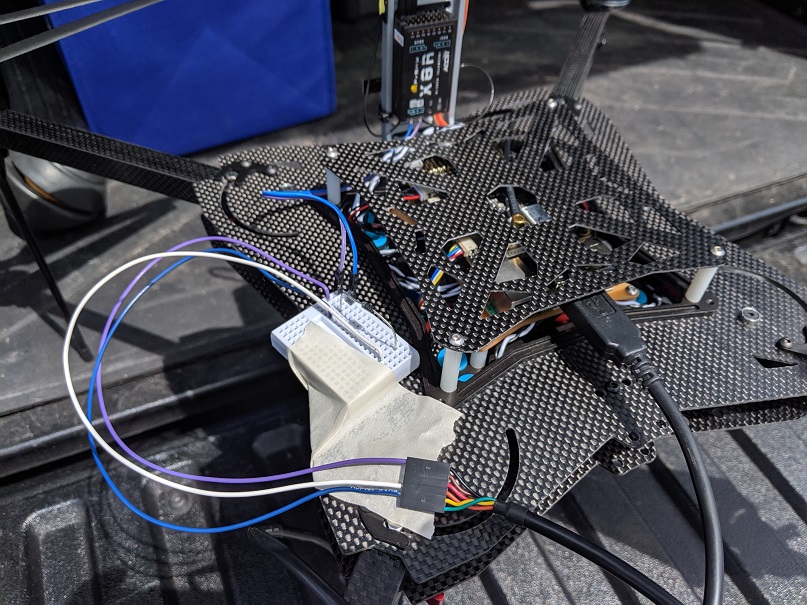
Here are some pictures:
Mission Planner Setup:

Taranis only finds RSSI and RxBT sensors, yaapu script is currently disabled

Excuse my crappy soldering job here, I was in a rush  The diode is soldered to the underside, in the correct orientation.

Am I overseeing something? My Hexa is running an X8R. Do I have to bind the X8R in a special way or jumper any pins or do some other magic? The reciever is bound in D16 Mode with Channels 1 to 8 with 8ms.
Any help is much appreciated.
has resistors on the serial port
on the serial port 5 there are no resistors I will solder the wires in it now for tests
Upper side and under side are different circuits, diode must be on same side as cables and all connections must be on the same side.
still does not work
my receiver is an X8R
I’m using this way
X8R> MLVSS> Matek F405-STD
sometimes those converter chips are dead on arrival, try the other one
works on Pixhawk 2.8