like this?
like this?
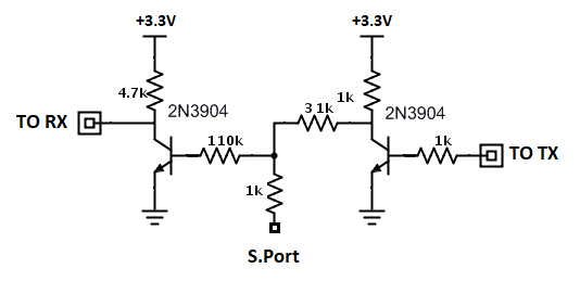
Thank you, this clarifies everything. So you’re basically using two inverters for the received signal as well. I’m guessing the diode should go on the “To RX part”?
In the example circuit from the OP while sending the FC-TX pin feeds “unwanted” bytes to the FC-RX pin but that is taken care of by software, while receiving the diode prevents the FC-TX pin from receiving incoming bytes directed to the FC-RX pin.
this particular circuit does not need a diode, only the one based on the MAX3232 needs it
I see, thank you very much, you won’t believe how many hours I spent trying to get this working. I was also confused because the OP doesn’t seem to be using an inverter anywhere, just an RS232 to TTL converter, which… I just realized inverts the signal both ways…
Luckily I think I have one somewhere, I will use that so I don’t need to use my two-inverter custom board. Thanks again!
Bah, still no luck  I used the TTL <-> RS232 adapter I had, but I didn’t have a regular diode so I put a 5.6V Zener diode on the pins (which I imagine should be fine), but still don’t get the GPS sensor. Maybe the Zener diode won’t actually work, or maybe I soldered it the wrong way around
EDIT: I found a diode and connected it like in the photo, still no luck. I can’t discover the GPS sensor on OpenTX 2.2.2 no matter what I do. Can anyone think of something I might be doing wrong? Maybe it’s a software problem?
I have tried reversing the pins, double-checking the diode, the connectors, the voltage (I don’t have an oscilloscope to test the communication, unfortunately), set the software to SPort passthrough for SERIAL4, deleted all telemetry and scanned again around a hundred times, but the GPS telemetry sensor never shows up.
Any ideas would be appreciated, I don’t know what else to try  Maybe there’s at least a way to see if the PixHawk communicates with the XSR at all?
my 2 first MAX3232 were defective, I ordered original one and it worked.
Oh wow, that’s a possibility? I’ll try a new one, thank you!
You were right, both modules were defective. I used two of my own inverters and telemetry appeared, thank you, everyone!
A link i i think is missing in this topic: https://oscarliang.com/uninverted-sbus-smart-port-frsky-receivers/ .
As we are all willing to do some soldering, why not get the uninverted signal instead of inverting it twice… (some pads are quite small tho)
Hi,
I just tested soldering to those pads mentioned on Oscar Liang’s website. It gives me weird results. It actually finds every sensors. But then they don’t get refreshed. Just like communication between rx and fc starts and then breaks.
Any ideas on what’s going on?
So,
https://github.com/ArduPilot/ardupilot/issues/9267#issuecomment-435619177
I got it working as explained in the linked issue.
Bridging rx and tx with a diode and soldering to pads on the back of the x4r.
As explained its only a hack waiting for the uart code to support half-duplex.
But hey it works without max3232 chips.
hi alex
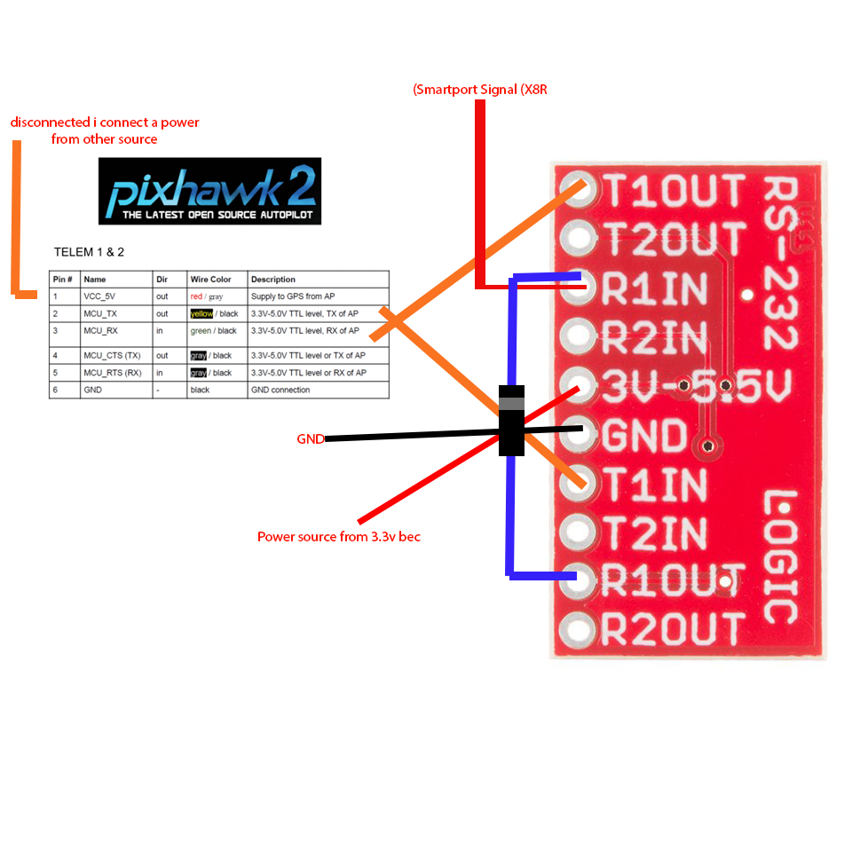
im trying to do that with SparkFun breakout board (rs232 to ttl converter) and i break my head for few days nothing work, here is how i connect the things
ill be happy if u will help me thanks
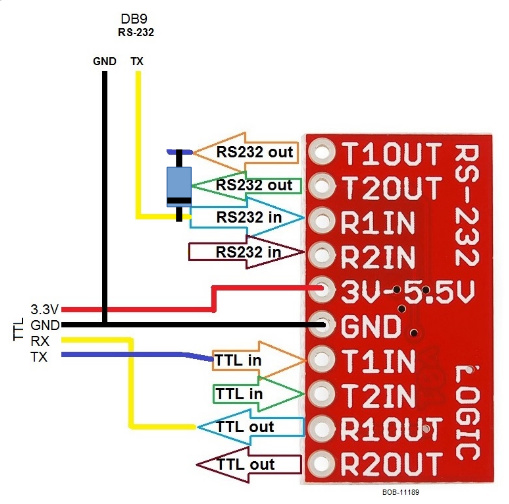
looks like you have it hooked up wrong,
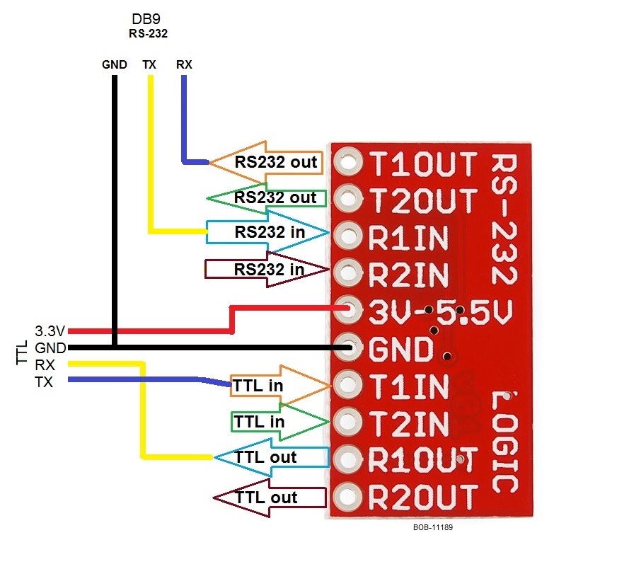
diode should go from R1IN to T1OUT in the above diagram, we dont have the blue RS-232 connected to T1OUT in this application.
Must say sparkfun’s pin labeling is quite confusing.
thanks for the answer i change it like your picture and still dont detect any sensor… maybe something else wrong? i did the ardupilot setting and set the SERIAL 1 to 10 there is something else i need to do?
I have never tried detecting sensors it should just start working in the telemetry script on you transmitter. you may have to clear any sensors you have set up.
You could try swapping to the second set of pins I guess (ie t2 r2) maybe having it connected wrong bust something. although they should be quite robust.
i upload the script and in the display section i choose i choose screen 1 Script - yaapu9 , thats all i need to do to get the the yaapu work? its show the telemetry screen but says “no telemetry data”
hi @Shayke_New,
you might be missing the diode between in/out to handle half duplex (in @iampete diagram would be between T1OUT and R1IN)
then, provided the board is working all you need is assign the script to one of the telemetry screens as explained here
Sensor discovery is optional, the script works fine without it.
There’s one exception: when the script does not run (it’s not assigned to a telemetry screen) you should be able to discover the GPS sensor anyway for is the only one provided by ardupilot when SERIALn_PROTOCOL is set at 10, all other sensors are “faked” by the script and exposed to OpenTX as a mean to access telemetry values from the radio.
Edit: corrected the diagram
hi @yaapu
thanks for your answer!
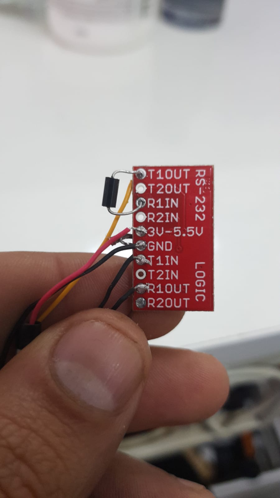
its look like i did it good i take picture for u how i did the soldering