Some soldering required

I used the circuit from this pdf. It’s in German but easy to follow. The converters made from this work perfectly on my Matek-F405 Wing and on my Pixhawk2. I already had all the parts on-hand too. I bought a collection of general purpose resistors, one of transistors, and one of capacitors just for fun, and they have really been helpful for simple DIY circuits. You can use 2N3904 transistors for this, but note the pinout is reversed from the BC547. The collector and emitter are swapped.

Just as a kind reminder when using with APM Plane: this is from the release notes page on github:

Release 4.0.3beta1, 10th January 2020

[…]
The most important fix is for FrSky pass-through telemetry. Pass

through telemetry support had a race condition which could lead to the

flight controller generating a fault and rebooting. Until you are

running a firmware with the fix you should disable FrSky pass-through

telemetry by changing SERIALn_PROTOCOL from 10 to 0 on the where you

have SPort enabled.

Happy flying!

Thought I would update this thread too, for the CUAV V5 Nano I was able to use a very basic 2-wire cable with just a pull-down resistor between the two wires, no other electronics required.

1 Like

Digging up this thread. I have been trying to make my own telemetry cable as per instructions in this thread. I cannot get it to work :frowning:

My board is based on MAX3232. I have checked my soldering, I have tried to swap TX and RX cables on the TTL side, checked cables and connectors. Everything seems to be fine. One funny thing you may notice is the LED diode which I put in because I don’t have a normal one handy. The functionality should be the same though and I actually do see it briefly flash which may be a good sign that something is happening.

I installed Yappu script on my Taranis and no matter what I do, no telemetry is showing. Any idea where to troubleshoot?

P.S. - I didn’t put in any pull up resistor, the board is not getting warm or hot.

Hi Alex, i have a quick question, how crossfire telemetry would work with this script?

1 Like

Nope, only frsky sport/fport.

thanks man for the quick response, i’m just trying to figure out to show data on my telemetry screen such as GPS cordinates etc

Hi all, I have a RX Jumper R1 + plus and I would like to use yaapu script with FC omnibus F4 nano V6.0. and radiomaster.

I need the outpus on S.port and therefore with F4 a non-inverting pad on the rx. I connected the serial TX1 (like in wiki) of the FC to the central pin of U5 (as in the picture pin 2), but I cannot read the telemetry data on S.port. On the RX I have not updated the FW.

What can I try?

Same RX works fine (normal connect with connector) with kakute F4 and S.port TLM

Thanks

non inv r1

I bought a couple of these max3232 cheap china boards from ebay and the first one has worked for about a year and does not get hot, never tried the second one till this week. It was not working, so I put a scope on it and found some of the through holes on the board (where you connect the wires to on the end of the board) were not making contact. I had soldered the two diodes to the bottom this time and the wires to the top.

And the diode that is connected to the S.Port was open (because of the open via) was showing the signal coming out of the rs3232 as +6 and -6 volts swing, then I remember rs232 signals are +/- voltages. S.Port is definitly not +/- voltages. When I got the diode connected properly, the minus portion was gone, I think it was being blocked by the diode, but the positive voltage was 6V going into the S.Port, that does not seem correct, thoughts?
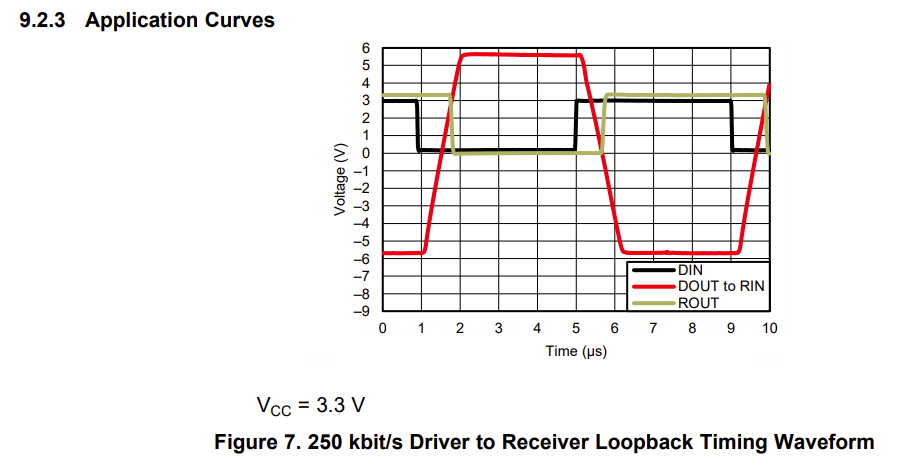
MAX3232 datasheet
https://www.ti.com/lit/ds/symlink/max3232.pdf?ts=1602176077680&ref_url=https%3A%2F%2Fwww.google.com%2F

I bought a couple Omnibus F4 V3 Pro flight controllers for use with AC and AP. I found this wire diagram on the net (not on Omnibus/Airbot) and it shows S.Port of a XSR “directly” connected to UART3 = I2C or Tx3/Rx3 (serial2 in MP) without a converter.

Ideas?

maybe there is some problem with the max3232 chip. we have made a converter cable like yours, it does not work too. so I bought this one. it does work.
https://www.amazon.com/dp/B07KJFWTCB

I am trying to connect my omnibus F4 nano v6.0 (6.0 version arducopter stable 4.0.5) to external inverter to have the yappu script on my master radio. My RX is a Jumper R1 + with S.port (tested on kakute F4 and yappu works fine). I have tried all the protocols on serial 1 of the FC omnibus (10, 23,4 baud rate 115,57 serial option 160, 0), but on the radio I don’t see the additional telemetry data. What can I try? I also connected TX1 output on pad RX and on TX of external inverter, but without success. Thanks

my FC

my inverter

my RX

I’ve had 100% success rate with these FrSky TTL/RS232 converters, they’re small, easy to wire up and cheap enough. This is my local source:

The wiring diagram on the Carbonbird web site is wrong, so use this:

I copied this diagram from the Ardupilot docs and took out the additional FrSky “diode on a circuit board” item and drew in how to add the diode yourself. Use a 1N4001 or 1N914, really any diode will do except an LED.
You can easily find connectors that fit onto the pins, or solder directly to the pins. You can even remove the connectors and solder directly to the board if you’re good enough :slight_smile:
I’ve found that the S-Port ground (0v) wire is optional too, since the flight controller, RC receiver and TTL converter all have a common ground anyway.

And these settings worked as per the suggestion in the docs:
SERIALx_BAUD,57
SERIALx_OPTIONS,160
SERIALx_PROTOCOL,10

Also I’ve had 100% success rate with external inverter form aliexpress (link above)

Hi I am trying to connect yapoo telemetry to Horus X10s express. I have Cube Orange, yaapo cable from aliexpress, Archer GR8, open tx 2.3.10, yapoo telemetry script installed on Horus X10S.

Yaapo cable is connected to Telemetry 1 connector so I am changing Serial_Protocol - 10 and tried all different options for SERIAL1_OPTIONS but without success. I can’t discover new sensors on telemetry screen. I also tried RC_OPTIONS - 8but didn’t help. Anyone with similar setup can help ?

Had such a problem that halted me for about a month… Does your receiver works as Fport or Sport ?

Yes it’s working. I found the solution: https://discuss.cubepilot.org/t/how-to-set-parameters-for-cube-black-and-cube-orange-for-yaapo-telemetry-by-s-port/5566/17

Hello, is anyone else having or had problems with the max3232 converter? I am connecting the tx(out) from cube to ttl side, arrow in, and the rx (in)from cube to the arrow out from ttl side, and I cant get telemetry readings and the chip gets hot very quickly, I am using a diode in series with vcc

I changed to another chip and its no getting hotter anymore, but I still can’t get telemetry data , can somebody please help? The max3232 is wired just like the guide, connected to the telemetry 2(Serial2 in mission planner with the baud to 57600 and the protocol set to 10, its the only port set to 10) I am using a frsky r9 receiver .

Can someone please help? I have no idea what could be the problem

After struggling with those MAX3232 from far east (some really get hot ), I connect a DVM and measure the current, those boards draw. With the good ones from China I see here between 10 to 15 mA. Ordered some MAX3232 from MAXIM and shall solder one on a board from China for comparison.

br KH