I solved the question. Below is an example project. The project can be considered as GPIO example.
//
// Simple test for GPIO reading signals.
//

#include <AP_HAL/AP_HAL.h>
#include <AP_BoardConfig/AP_BoardConfig.h>


//#include <AP_HAL/AP_GPIO.h>


// board specific config
AP_BoardConfig BoardConfig;

const AP_HAL::HAL &hal = AP_HAL::get_HAL();


#define		my_pin	50


void setup(void);
void loop(void);


void setup(void)
{
    BoardConfig.init();
	hal.gpio->pinMode ( my_pin , HAL_GPIO_INPUT  ) ;
	hal.gpio->init() ;

}


void loop(void)
{

    static int count = 0 ;
    // wait for user input

    while (!hal.console->available()) {
        hal.scheduler->delay(20);
    }

	hal.gpio->toggle(my_pin) ;

	uint8_t status = hal.gpio->read(my_pin) ;

    hal.console->printf("hal.gpio[%2d] - %d \t\t   count -   %5d \n", my_pin, status, count++) ;
    hal.scheduler->delay(1000);


}


AP_HAL_MAIN();
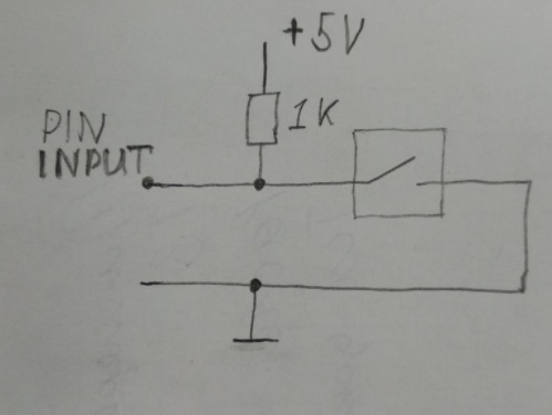
Hello everybody. I set up the spray system on pixhawk. now I want to integrate the water level sensor. The sensor outputs either 0 or 5V. I want to read the values through the AUX channel, but I do not understand how to do this.
Using examples from the libraries folder and the AP_Relay library, I learned how to program the feet of aux as output and send signals to them. Now I’m working with input signals.
I found a suitable AP_Buttons library and made the following settings: In the AP_Button.cpp file I made the presets in the var_info array to include the feet of AUX1-4. Then added the “get_button_status” method to read the mask changes.
That’s what all the code looks like.
AP_Button.h file
#include <AP_HAL/AP_HAL.h>
#include <AP_Param/AP_Param.h>

// allow buttons for up to 4 pins
#define AP_BUTTON_NUM_PINS 4

// how often we send reports
#define AP_BUTTON_REPORT_PERIOD_MS 1000

class AP_Button {
public:
    // constructor
    AP_Button(void);

    static const struct AP_Param::GroupInfo var_info[];

    // update button state and send messages, called periodically by main loop
    void update(void);

	// MY NEW METOD TO READ MASK
	// return status of current button
	bool get_button_status ( uint8_t button ) ;

private:
    AP_Int8 enable;
    AP_Int8 pin[AP_BUTTON_NUM_PINS];

    // number of seconds to send change notifications
    AP_Int16 report_send_time;

    // last button press mask
    uint8_t last_mask;

    // when the mask last changed
    uint64_t last_change_time_ms;

    // time of last report
    uint32_t last_report_ms;

    // has the timer been installed?
    bool initialised:1;

    // called by timer thread
    void timer_update(void);

    // get current mask
    uint8_t get_mask(void);

    // send a BUTTON_CHANGE report
    void send_report(void);

    // setup pins as pullup input
    void setup_pins();
};
AP_Button.cpp file.
#include "AA_Button.h"
#include <GCS_MAVLink/GCS_MAVLink.h>
#include <GCS_MAVLink/GCS.h>

extern const AP_HAL::HAL& hal;


const AP_Param::GroupInfo AP_Button::var_info[] = {

// @Param: ENABLE
// @DisplayName: Enable button reporting
// @Description: This enables the button checking module. When this is disabled the parameters for setting button inputs are not visible
// @Values: 0:Disabled, 1:Enabled
// @User: Advanced
AP_GROUPINFO_FLAGS("ENABLE", 0, AP_Button, enable, 0, AP_PARAM_FLAG_ENABLE),

// @Param: PIN1
// @DisplayName: First button Pin
// @Description: Digital pin number for first button input.
// @User: Standard
// @Values: -1:Disabled,50:Pixhawk AUXOUT1,51:Pixhawk AUXOUT2,52:Pixhawk AUXOUT3,53:Pixhawk AUXOUT4,54:Pixhawk AUXOUT5,55:Pixhawk AUXOUT6,111:PX4 FMU Relay1,112:PX4 FMU Relay2,113:PX4IO Relay1,114:PX4IO Relay2,115:PX4IO ACC1,116:PX4IO ACC2
//AP_GROUPINFO("PIN1",  1, AP_Button, pin[0], -1),

	// MY CHANGES
	AP_GROUPINFO( "PIN1",  1, AP_Button, pin[0], 51 ),  // 51 - pixhawk AUXOUT2 INPUT

// @Param: PIN2
// @DisplayName: Second button Pin
// @Description: Digital pin number for second button input.
// @User: Standard
// @Values: -1:Disabled,50:Pixhawk AUXOUT1,51:Pixhawk AUXOUT2,52:Pixhawk AUXOUT3,53:Pixhawk AUXOUT4,54:Pixhawk AUXOUT5,55:Pixhawk AUXOUT6,111:PX4 FMU Relay1,112:PX4 FMU Relay2,113:PX4IO Relay1,114:PX4IO Relay2,115:PX4IO ACC1,116:PX4IO ACC2
//AP_GROUPINFO("PIN2",  2, AP_Button, pin[1], -1),

	AP_GROUPINFO( "PIN2",  2, AP_Button, pin[1], 52 ),   // 52 - pixhawk AUXOUT3 INPUT

// @Param: PIN3
// @DisplayName: Third button Pin
// @Description: Digital pin number for third button input.
// @User: Standard
// @Values: -1:Disabled,50:Pixhawk AUXOUT1,51:Pixhawk AUXOUT2,52:Pixhawk AUXOUT3,53:Pixhawk AUXOUT4,54:Pixhawk AUXOUT5,55:Pixhawk AUXOUT6,111:PX4 FMU Relay1,112:PX4 FMU Relay2,113:PX4IO Relay1,114:PX4IO Relay2,115:PX4IO ACC1,116:PX4IO ACC2
AP_GROUPINFO("PIN3",  3, AP_Button, pin[2], -1),

// @Param: PIN4
// @DisplayName: Fourth button Pin
// @Description: Digital pin number for fourth button input.
// @User: Standard
// @Values: -1:Disabled,50:Pixhawk AUXOUT1,51:Pixhawk AUXOUT2,52:Pixhawk AUXOUT3,53:Pixhawk AUXOUT4,54:Pixhawk AUXOUT5,55:Pixhawk AUXOUT6,111:PX4 FMU Relay1,112:PX4 FMU Relay2,113:PX4IO Relay1,114:PX4IO Relay2,115:PX4IO ACC1,116:PX4IO ACC2
AP_GROUPINFO("PIN4",  4, AP_Button, pin[3], -1),

// @Param: REPORT_SEND
// @DisplayName: Report send time
// @Description: The duration in seconds that a BUTTON_CHANGE report is repeatedly sent to the GCS regarding a button changing state. Note that the BUTTON_CHANGE message is MAVLink2 only.
// @User: Standard
// @Range: 0 3600
AP_GROUPINFO("REPORT_SEND", 5, AP_Button, report_send_time, 10),

AP_GROUPEND
};


// constructor
AP_Button::AP_Button(void)
{
    AP_Param::setup_object_defaults(this, var_info);
}

/*
  update and report, called from main loop
 */
void AP_Button::update(void)
{
    if (!enable) {
        return;
    }

    // call setup pins at update rate (5Hz) to allow for runtime parameter change of pins
    setup_pins();

    if (!initialised) {
        initialised = true;

        // get initial mask
        last_mask = get_mask();

        // register 1kHz timer callback
        hal.scheduler->register_timer_process(FUNCTOR_BIND_MEMBER(&AP_Button::timer_update, void));
    }

    if (last_change_time_ms != 0 &&
        (AP_HAL::millis() - last_report_ms) > AP_BUTTON_REPORT_PERIOD_MS &&
        (AP_HAL::millis64() - last_change_time_ms) < report_send_time*1000ULL) {
        // send a change report
        last_report_ms = AP_HAL::millis();

        // send a report to GCS
        send_report();
    }
}

/*
  get current mask
 */
uint8_t AP_Button::get_mask(void)
{
    uint8_t mask = 0;
    for (uint8_t i=0; i<AP_BUTTON_NUM_PINS; i++) {
        if (pin[i] == -1) {
            continue;
        }
        mask |= hal.gpio->read(pin[i]) << i;
    }
    return mask;
}

/*
  called at 1kHz to check for button state change
 */
void AP_Button::timer_update(void)
{
    if (!enable) {
        return;
    }
    uint8_t mask = get_mask();
    if (mask != last_mask) {
        last_mask = mask;
        last_change_time_ms = AP_HAL::millis64();
    }
}

/*
  send a BUTTON_CHANGE report to the GCS
 */
void AP_Button::send_report(void)
{
    uint8_t chan_mask = GCS_MAVLINK::active_channel_mask();
    uint32_t now = AP_HAL::millis();
    for (uint8_t i=0; i<MAVLINK_COMM_NUM_BUFFERS; i++) {
        if ((chan_mask & (1U<<i)) == 0) {
            // not active
            continue;
        }
        mavlink_channel_t chan = (mavlink_channel_t)i;
        if (HAVE_PAYLOAD_SPACE(chan, BUTTON_CHANGE)) {
            mavlink_msg_button_change_send(chan,
                                           now,
                                           (uint32_t)last_change_time_ms,
                                           last_mask);
        }
    }
}

/*
  setup the pins as input with pullup. We need pullup to give reliable
  input with a pulldown button
 */
void AP_Button::setup_pins(void)
{
    for (uint8_t i=0; i<AP_BUTTON_NUM_PINS; i++) {
        if (pin[i] == -1) {
            continue;
        }
        hal.gpio->pinMode(pin[i], HAL_GPIO_INPUT);
        // setup pullup
        hal.gpio->write(pin[i], 1);
    }
}

// MY NEW METOD TO READ MASK
// return status of conkretic button.
// buttons number: 1-4
bool AP_Button::get_button_status ( uint8_t button )
{
	uint8_t mask = get_mask();
	//  last_mask - status of all buttons
	if (mask & ( 0b1 << button ) ){
		return true ;
	}
	return false ;
}
MAIN file
//
// Simple test for the AP_InertialSensor driver.
//

#include <AP_HAL/AP_HAL.h>
#include <AP_BoardConfig/AP_BoardConfig.h>
#include <AP_InertialSensor/AP_InertialSensor.h>
#include <stdio.h>
#include <AP_Button/AP_Button.h>

const AP_HAL::HAL &hal = AP_HAL::get_HAL();

AP_InertialSensor ins;
// board specific config
AP_BoardConfig BoardConfig;
AP_Button v_button ;

void setup(void);
void loop(void);

void setup(void)
{
    // setup any board specific drivers
    BoardConfig.init();

   //  RELAY INIT
    //v_relay.init() ;

    ins.init(100);

   v_button.update();
}


void loop(void)
{

    static int count = 0 ;
	int i ;
    // wait for user input

    while (!hal.console->available()) {
        hal.scheduler->delay(20);
    }

	v_button.update();
	hal.console->printf("%5d)Button status =  ", count++);

	for (i = 7; i>=0 ; i-- ){
		hal.console->printf("%s", v_button.get_button_status (i) ? "1" : "0") ;
		hal.scheduler->delay(10);
	}
	hal.console->printf("\n");


    hal.scheduler->delay(1000);

}


AP_HAL_MAIN();
After uploading the project to pixhawk, I feed into the AUX2 channel of 0V or 5V, but I do not see any changes in the console.
MAV> Waiting for heartbeat from COM12
    0)Button status =  00000000
    1)Button status =  00000000
    2)Button status =  00000000
    3)Button status =  00000000
    4)Button status =  00000000
    5)Button status =  00000000
    6)Button status =  00000000
    7)Button status =  00000000
    8)Button status =  00000000
    9)Button status =  00000000
   10)Button status =  00000000
   11)Button status =  00000000
   12)Button status =  00000000
   13)Button status =  00000000
Be kind, direct me towards the solution of the problem.