Hi everyone,
So recently I purchased a skyviper fury. As I understand it, this drone runs a version of ardupilot and flies using the optical flow sensor. I was pretty impressed with it’s ability to hold position and was hoping to do some bench testing with the internal board and sensor. I have torn down the drone since it only cost me $29.99 and I would love to be able to upload custom firmware for testing. With that being said I have a few questions that hopefully someone can answer.
Does anyone know what the waf board type is to build for this aircraft? I found this in another thread but am not sure which is correct https://discuss.ardupilot.org/t/build-ardupilot-for-2018-scout/34586
yes, use this branch: https://github.com/SkyRocketToys/ardupilot/commits/skyviper2018
build it with: ./waf configure --board skyviper-f412
then: ./waf copter
then another comment stating:
I think skyviper-f412 is for Journey GPS and skyviper-f412-512k is for Scout.
Is scout build the same for fury? I am inclined to assume it is since it flies via the same optical flow sensor, the only difference being the onboard streaming camera on scout.
What is the default flight mode for this aircraft? Is it using flow hold?
What is the type of sensor on-board? Based on reading commit notes on the skyrocket ardupilot repo, I assume it is a Pixart 3901 and if so, does anyone know of an off the shelf version of this sensor for use with regular pixhawk flight controllers?
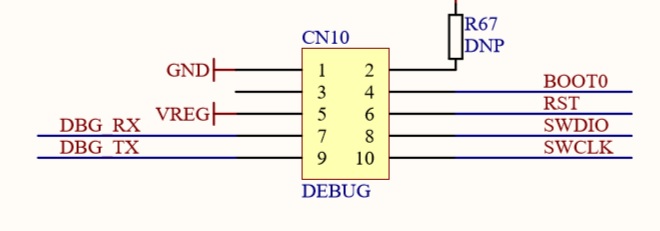
This question is a little more technical, can anyone recommend a method for identifying the pads labeled as CN10 in the images below? I am hoping it is the usb port, but I can’t be sure. Is there any way to identify these pins? Maybe with an oscilloscope? If anyone knows, please let me know.
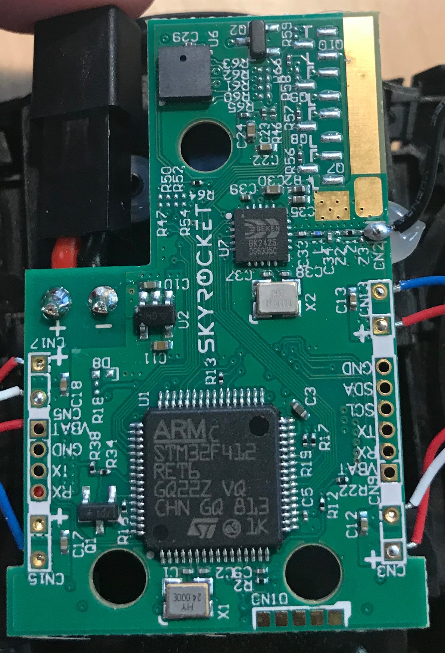
Back Side of Board
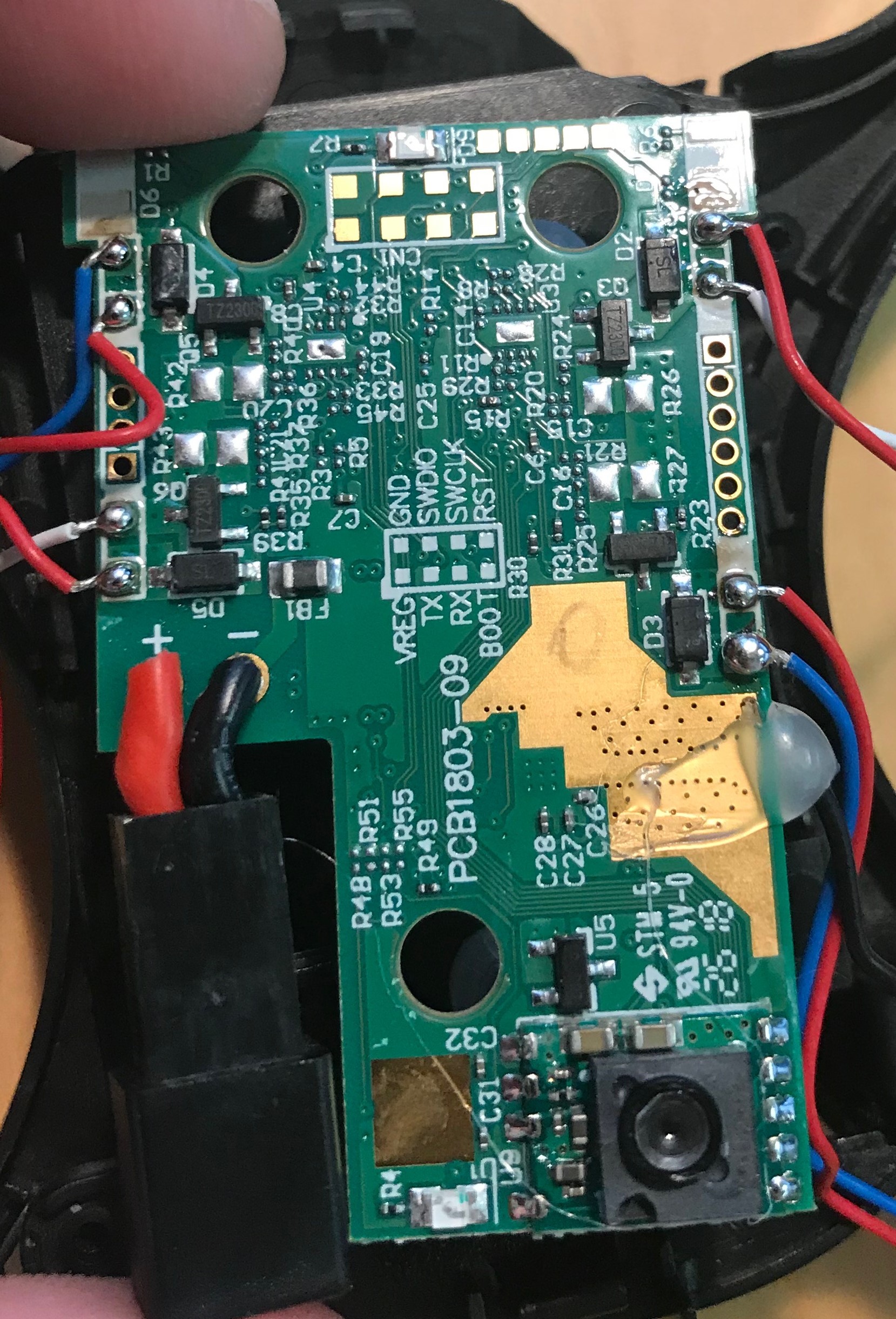
Front Side of Board w/ Downward facing sensor
Final Question, I am assuming I would have to flash firmware via the debug pads on the front side of the board with my black magic probe, unless CN10 is a USB interface.
If anyone has any experience with these new skyviper products or insight into my questions, any information would be greatly appreciated.
Thanks everyone,
James