Hello, I’ve APM 2.8 which is working fine when we connect it to mission planner through usb cable. GPS and compass working properly, but telemetry 433mhz can’t communicate with each other, “no heartbeat packet recieved” msg shown after 30 sec timeout. I also check by changing tx-rx connection. If anybody have solution, it is very helpfull to us. Many thanks in advance.
Check the baudrate in config of APM and mission planner connection option.
Is the red light on telemetry blinking?
Yes red light turn on when I connect it to laptop through ftdi to usb converter. Baudrate shown 57 and data is attached.
If you can see some data incoming through comport, maybe problem in settings of your apm. Check this manual http://ardupilot.org/copter/docs/common-telemetry-port-setup-for-apm-px4-and-pixhawk.html
1 Like
Could be a lot of things:
Not sure what kind of radios you have. Do they have LEDs? If they do and they are flashing that means your radios are connected. This coud be caused by improper wiring on either radio, different NET ID in the radios, wrong baud rate or configuration of the comm port.
Here is a link to an excellent guide. http://ardupilot.org/copter/docs/common-3dr-radio-advanced-configuration-and-technical-information.html
1 Like
I had the same problem - FIXED.
The Air unit config was different to the ground.
I had to connect the Air unit to laptop using FTDI board.
Then loaded settings using MP & removed the ticked boxes for ECC & Op Resend.
Saved back to board & it immediately connected.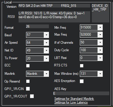
How did you connect the air module using a FTDI board?
Take it out of the case. Connect Volt to Volt, ground to ground, TX to RX, RX to TX.
I can’t solder them or connect them one to another,
one has usb which connects to computer (no other components to solder/connect on it)
and the second one already has a solder case in it which has 4 connections (gnd vcc rx tx)
can u check my thread here please:
Configure the ground unit how you need it. It sounds like you’ve already done that. Now remove the air unit from it’s case. Use USB Arduino board & connect it’s pins to the air unit pins, as per previous post… Connect the pins together using custom dupont cables.
Now connect the arduino board to computer using it’s usb port. Now it acts just like the ground unit & you can configure it the same way  Make sure it is configured same as Ground unit. It took me a while to figure it out. Good luck.
Once both untis are configured the same, disconnect usb Arduino, disconnect Air unit from Arduino & now you should get communication between them both.
Are you familiar with configuring & using FTDI (Arduino) boards?