Gazebo is capable of simulating a variety of sensors, however the current support for returning sensor data back to ArduPilot SITL is limited. In this article we look at using DroneCAN to publish simulated sensor data.
To understand why this is an attractive proposition, we start with a quick review of the current mechanism by which ArduPilot SITL and Gazebo communicate.
On the ArduPilot SITL side the communication is managed by the objects in SIM_JSON. For Gazebo it is the system plugin ArduPilotPlugin. Communication is via UDP: ArduPilot sends a binary packet containing a vector of servo outputs (PWM), and Gazebo replies by sending a JSON payload containing the state of the flight dynamics model. The process is lock-stepped, so if either side pauses the other waits. This allows step debugging of either the Gazebo simulation, or the ArduPilot flight controller, or both at the same time.
The JSON model supported by SIM_JSON is described in a SITL library README. In addition to the core attitude information required for control, the following optional sensor data is supported: up to six range values, apparent wind direction and speed, and airspeed.
While the JSON model is extensible, there are some drawbacks:
- The data is sent at the physics loop rate. This is approximately 1000 Hz for most of the ArduPilot Gazebo examples. Many of the sensors we are interested in sample at much lower frequencies - typically around 20 Hz to 50 Hz.
- Adding sensor fields requires coordinated changes to both the
ArduPilotPluginandSIM_JSON. - The data transport and message format for the sensor data doesn’t correspond to that used by real hardware, so it’s not a like-for-like substitute.
DroneCAN provides a way to address these issues:
- The data rate for each sensor message may be customised.
- The approach uses existing DroneCAN sensor backends in ArduPilot.
- The data transport and message format are exactly the same as for real devices.
Example: ESC status from an Iris quadcopter
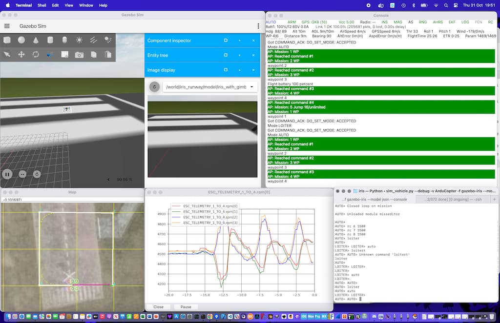
The iris quadcopter is one of the reference models provided in the ardupilot_gazebo repo. We would like to report the rotor RPM values back to the FC and be able to display and log this in a GCS such as MAVProxy.
Approach
For a demonstration we use a Python script to subscribe to joint velocities and publish them as DroneCAN messages. This makes use of the Python bindings to the Gazebo
gz.msgs and gz.transport libraries and pydronecan.
- Use
JointStatePublisherplugin to publish joint positions and velocities - Use the Python bindings to
gz.msgsandgz.transportto subscribe to thegz.msgs.Modelmessage published by theJointStatePublisher. - Filter the model joints by name to extract the rotor joints.
- Read the joint velocity and convert to RPM.
- In a separate thread run a
dronecannode that publishesdronecan.uavcan.equipment.esc.Status. - Push the RPM updates from the rotors to the
dronecannode. - Set the parameter
CAN_D1_UC_ESC_BM = 15to enable the first 4 motors as DroneCAN ESCs.
Details
The following branch contains the Python script and update models to support publishing rotor RPM.
- The
gimbal_small_3dandiris_with_gimbalmodels are modified to use themerge=trueattribute when composing models. This is to workaround a bug in theJointStatePublisherwhich does not publish the joints of nested models. - The Python script
dronecan_sensors.pyprovides the bridge between Gazebo and DroneCAN.
Running
Check out the branch, then start the Gazebo sim.
gz sim -v4 -r iris_runway.sdf
Start the SITL instance
sim_vehicle.py --debug -v ArduCopter -f gazebo-iris --model json --console
Configure the CAN parameters in MAVProxy
STABILIZE> param diff CAN*
STABILIZE>
Parameter        Current  Default
CAN_P1_DRIVER    1.000000 0.000000 # First driver (DEFAULT: Disabled)
CAN_P2_DRIVER    1.000000 0.000000 # First driver (DEFAULT: Disabled)
CAN_D1_UC_ESC_BM 15.000000 0.000000 #  ESC 1| ESC 2| ESC 3| ESC 4 (DEFAULT: )
A reboot is required after setting the CAN params.
Run the dronecan script
python dronecan_sensor.py mcast:0 --node-id 100
Plot the ESCs in MAVProxy
graph ESC_TELEMETRY_1_TO_4.rpm[0] ESC_TELEMETRY_1_TO_4.rpm[1] ESC_TELEMETRY_1_TO_4.rpm[2] ESC_TELEMETRY_1_TO_4.rpm[3]
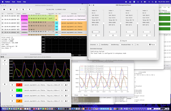
Use the dronecan_gui to inspect the bus and plot the RPM levels.
Known Issues
- The
JointStatePublisherissue needs to be fixed upstream as the workaround does not scale well. - ESC voltage, current, temperature, are populated with mock values as the simulation currently provides no estimate for these.
Next Steps
There are a number of sensor systems in Gazebo that could be published to ArduPilot using this approach:
- AirPressure
- AirSpeed
- Altimeter
- Magnetometer
- NavSat

