Scripting Copter Wind Estimation/Baro Compensation Tuning

In his outstanding presentation referenced in the Copter documentation, @priseborough discusses the possibility of creating a script to help with the somewhat cumbersome tuning process for wind estimation and baro compensation on multirotors.

I took a stab at such a script this month and came up with something that seems to be working for autotuning the momentum drag coefficient.

Wind is estimated based on GPS course and AHRS velocity during a downwind, level attitude drift in guided mode. Thereā€™s no direct/clean way to manipulate yaw in the current Lua bindings, so Iā€™m using guided mode to set attitude targets during the weathervaning phase. For best results, wind conditions should be fairly consistent, and the copter should be allowed to drift downwind until it is facing upwind and drifting at constant velocity (at wind speed). EK3_DRAG_BCOEF_X and Y must have already been computed and saved.

To use the script, first edit the top few environmental parameters with current temperature, baro pressure, and relative humidity. Load the script onto the SD card and be sure that scripting is enabled. Set an aux RC channel to RC_OPTION=300, preferably on a momentary switch. Upon boot, you should see a GCS message declaring the script ready, along with the computed air density value. Thereafter:

  • Tune your copter well beforehand, and be sure the airfield is well clear for maneuvering.
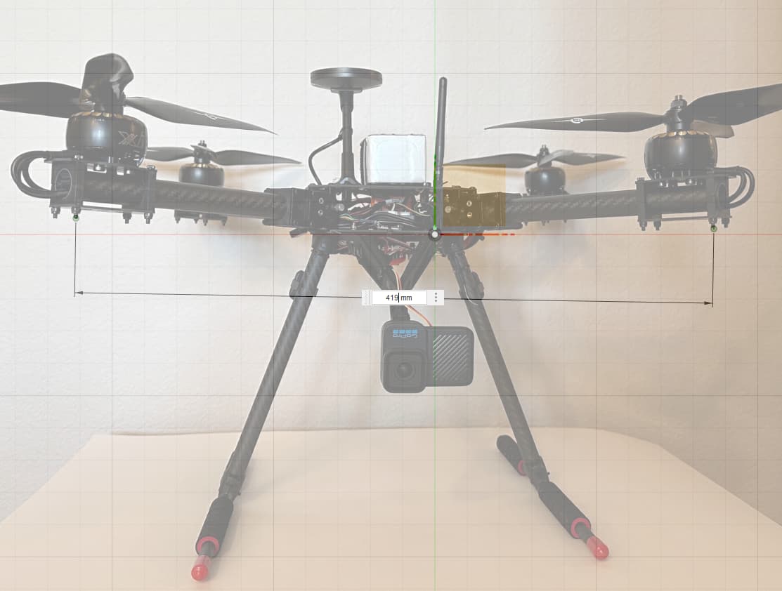
    • As discussed in the presentation, youā€™ll need at least 50m clear of obstacles, and preferably a few hundred meters in all directions.
  • Take off and hover in loiter, position hold, or altitude hold with the transmitter sticks neutral.
  • Hold the assigned aux switch for at least one second and release it.
  • The copter will begin drifting with the wind, aligning the nose upwind.
  • Push the pitch stick full forward to accelerate into the wind.
  • When maximum speed is achieved, release all sticks to neutral.
  • After decelerating, the copter will be switched to loiter mode and is ready for further tuning or flying.
  • Hold the aux switch for less than one second and release to set the orientation to LEFT.
  • Repeat the long press, drift, and upwind run for each orientation, being sure to only accelerate directly into the wind using pure (single axis) pitch or roll RC stick inputs each time.

The weathervaning (drifting) phase can be canceled at any time by toggling the aux switch, moving the throttle, or changing flight modes.

Youā€™ll see GCS text output that looks something like this:

Complete! Momentum drag coefficient = 0.117
Measuring momentum drag
Awaiting level attitude, max airspeed 13.6 m/s
Max speed achieved, center sticks
Wind estimated 110 at 1.5 m/s
Weathervaning (NOSE into wind)

After landing and disarming, the average of all runs will be saved to EK3_DRAG_MCOEF.

If you wish to check results, arm and take off again. Watch for periodic AHRS wind messages and compare them against observed wind or enter the weathervaning phase and cancel it to get a wind measurement independent of the drag coefficients.

I couldā€™ve used custom parameters for temp, baro pressure, and relative humidity, but since this script will probably only be run once and then discarded, I thought that was unnecessary.

Definitely open to feedback!

copter-weathervane_draft-rev3.lua (13.7 KB)

7 Likes

As a slight aside, Fusion 360 can be used to estimate frontal/side area by inserting pictures as canvas objects.

First calibrate for scale:

Then create a sketch and trace the outline of your copter using lines and/or splines, estimating where perspective skews the image. Set the document units to cm, and use the measuring tool to select the shape enclosed by your sketch.

The first 15 minutes or so of this video describe inserting/calibrating a canvas and beginning to trace it:
Fusion 360 Absolute Beginner - How To Model a Spark Plug

1 Like

Placeholder for now - first posts contain relevant info.

Great idea!
I wonder if we can estimate drag coefficients by circling at constant speed, with first nose to front, then nose to side.
The average throttle minus hover throttle in the circle should tell us the drag. For example if average throttle is 25% over hover throttle then we know drag force is mass times 9.81/4.
This automatically cancels for wind and gives a more controlled test. If we want multiple points on the drag curve we can just circle at different speeds.
This would work better after running the expo script so we know throttle mapping to accel is right.

Interesting!

The script at present is essentially just attempting to abstract the log review and manual arithmetic away from @priseboroughā€™s approach in the conference presentation. I was hoping for some testing/feedback before including/attempting a method for baro comp values, but there was zero response, so I let it go. Maybe I shouldā€™ve made the title more of a request for testers than just a bland statement.

I can give circling a go and compare results. It looks like CIRCLE_MODE with various CIRCLE_OPTIONS can be used to easily accomplish at least a proof of concept.

Started a script using circle mode as you describe. I have to brush up on my engineering formulas to get from drag force to a useful drag coefficient, but I think I have a good start published to my AP fork.

ardupilot/copter-circle-drag.lua at circle-drag-tuning-script Ā· yuri-rage/ardupilot Ā· GitHub

Interestingly, because circle mode targets an angular rate, you can just adjust the size of the circle to gather points along the drag curve (up to WPNAV_SPEED).

Just wondering how this would work in comparison to the current method. The current method requires level attitude (as your described in your initial post), but having this happen in Circle mode means that the attitude will not be level. The drag coefficient of a multirotor is obviously different depending on attitude - so how are we handling this?

There are definitely some nuances to wrap my brain around. Iā€™m not yet certain where the pitfalls lie, and where concessions must be made.

@tridge, I see your expo script runs at a high sample rate with a low pass filter on the throttle values, but the throttle pulses are a much more dynamic maneuver than a constant rate turn. Do you think thereā€™s value in increasing the sample rate and filtering the throttle values in this script?

thanks! I think what we should do is try calculating some drag values in SITL and see if they match.
hmm, I thought we had SIM parameters for drag available ā€¦ now I go to look I canā€™t see them. libraries/SITL/SIM_Frame.cpp just has drag derived from an area.
So I think we need to add SIM_VTOL_BDRAG_{X,Y,Z} and SIM_VTOL_MDRAG parameters with same units as the EKF3 ballistic drag and momemtum drag parameters. If non-zero these would override the current drag calculations in SIM_Frame. We should probably move the SIM_VTOL parameters to their own param subtree in SITL.cpp.
We can use this to test that the lua script is working correctly by trying different values for the ballistic and momentum drag and ensuring we converge on the same (or at least similar) values. That also forms the basis for an autotest.

1 Like

I was thinking weā€™d use a radius and speed where the lean angle towards the center is fairly small, but youā€™re right that this will cause some degree of error. I wonder how big of an effect this is?

It should be possible to compensate for radial component as it consists only of centrifugal acceleration compensation so |a_D|=āˆš(a_H^2-a_C^2) where a_H^2=(1+a_ThE)^2-1 a_C=V^2/R

a_ThE is acceleration caused by excessive thrust. Need accurate thrust expo for that.
a_H is horizontal acceleration assuming constant altitude.
a_C is centrifugal acceleration
a_D is ā€œdrag accelerationā€ how fast we would be accelerating if we were in hover at this attitude.

There is one source of errors, we arenā€™t compensating for, namely lift. AFAICT it will typically increase thrust needed to maintain constant altitude. The question is how this will affect wind estimation especially compared to copter mass changes.

I was more referring the the lean angle tangent to the circle (in direction of flight). I think it is relatively safe to assume (for now) that the lean angle towards the center would be fairly negligible if the aircraft is well tuned.

1 Like

The current system already ignores lift and works reasonable well - so I think it is safe to continue with the assumption that lift is a negligible source of error.

1 Like

Next step is to get from calculated drag force to momentum drag coefficient. Assuming I have area drag coefficients already calculated, thatā€™s probably not difficult, but Iā€™m sure one of you will quickly recommend an appropriate formula/method that I will have to research otherwiseā€¦ A little help?

We can move on to testing and modifying SITL to suit from there.

The method currently used to calculate momentum drag from total drag requires the aircraft to have level attitude during the flight. So - we would need to figure out a different route if we are using circle mode.

Manav, I do understand the nuance there, but I think Tridgeā€™s idea is to ignore the minor pitch/roll attitude of a large enough circle and apply the existing methodology. With that assumption, can you recommend a method to get from here:

to a valid X/Y MCOEF parameter?

Or am I over-simplifying things?

I donā€™t quite understand the minor attitude thing because you will def have major attitude in the direction of motion (tangent to the curve). The drag will occur in the direction of motion and thus will be effected by the large attitude.

Iā€™m not sure weā€™d always have a ā€œmajorā€ attitude in the direction of travel, but perhaps at the most useful points on the drag curve (higher speeds) the attitude may be non-negligible. Understood. Iā€™d just like to move things forward, and Iā€™m a bit stuck, despite some depth of knowledge on the subject (but not a graduate engineering degree, nor industry experience).

Yeah I am assuming we are targeting the 15+ m/s speeds achieved during the current testing. Which would be at least a 15 to 20 degree attitude for most aircraft.

1 Like

So one way to do this is to use circle mode to build up airspeed in a compact area and then switch out of circle mode (into alt hold mode) for the actual data collection. We donā€™t really care about the data during the airspeed build up in the current testing methodology, the idea just seems to be that the more airspeed we gain before data collection - the longer time period of data we will have for analysis. Once the aircraft speed has stabilized (flowing with the wind and no acceleration) we can then switch into loiter/RTL/etc. to close out the tuning process.

This isnā€™t much better than our current method though because we do still need to spend time in alt-hold more for the data collection period.