Hi!
I’ve set up my Kore Carrier board and soldered everything together. However, Mission Planner doesn’t show my SBUS input. I’ve connected the receiver to the SBUS port on the Kore board and I’ve verified with two receivers and my mini carrier board that everything works but not here. Also, every time I exit and re-enter the Radio Calibration page on Mission Planner, a new rc1 is appended in the bars…
Thanks!
I believe the pins labelled SBUS are for SBUS Out (to gimbal and so on)
and what you need is the pins (incorrectly) labelled PPM, which should be RCIN.
Yeah!
Once I started messing around by moving it to the PPM pin it worked. Maybe we can recommend this change be made in their next revision of boards? How would we do that?
Sounds good. I think they should be able to change the silkscreen when they manufacture new PCBs…maybe?
Thanks for this! What a relief. I almost a whole day trying to figure this out. One quick note for posterity’s sake:
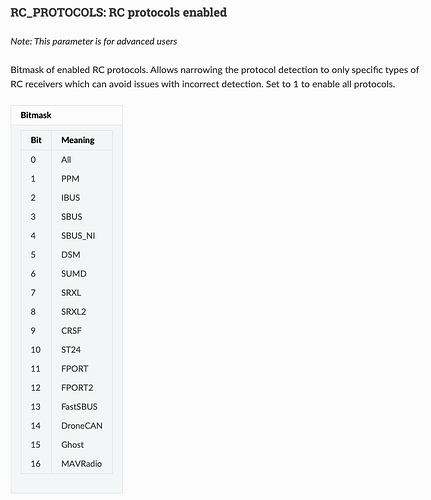
The RC_PROTOCOLS Arducopter parameter has to be set to 1 for this to work, which is weird because this according to the documentation, 1 is associated with PPM. I had it set to 0 (All) and 3 (Sbus) and those didn’t work. Not sure why this parameter has to be set this way if this is truely on the a silk screen error on the board.
RC_PROTOCOLS is a bitmask parameter. So as per the docs, 1 will give you all.
RC_PROTOCOLS: RC protocols enabled
Note: This parameter is for advanced users
Bitmask of enabled RC protocols. Allows narrowing the protocol detection to only specific types of RC receivers which can avoid issues with incorrect detection. Set to 1 to enable all protocols.
I see that in the description now (thanks), but what am I missing because the table has 0 listed as ‘All’:
As Allister already wrote, RC_PROTOCOLS is a bitmask parameter. In the table you are looking at the bits to set for each function, not the absolute values. So bit 0 = 20 = 1, bit 1 = 21 = 2, bit 2 = 22 = 4 and so on.
